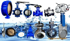
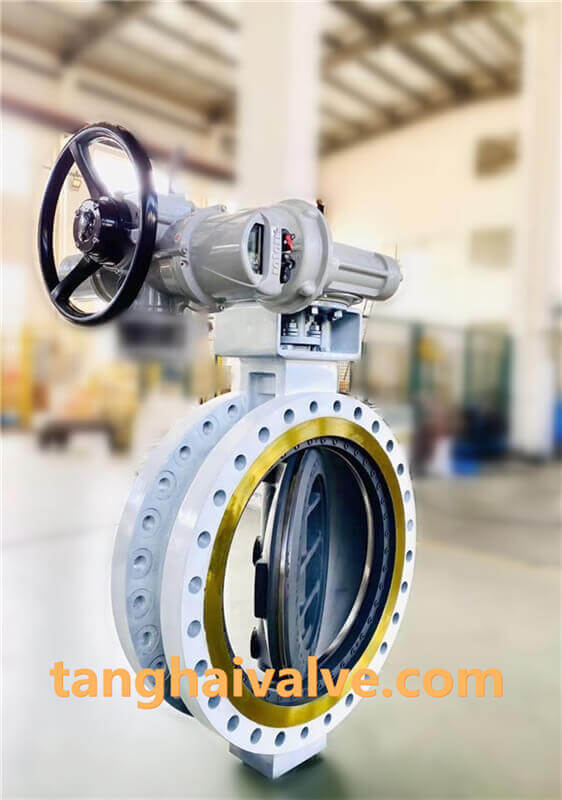
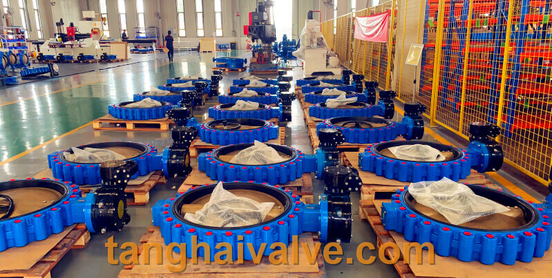
Types and classifications of butterfly valves

Types and classifications of butterfly valves
Butterfly valves can be divided into offset plate type, vertical plate type, inclined plate type and lever type according

ductile iron, DI, butterfly valve, manufacturer, center line, TH valve

ductile iron, DI, butterfly valve, manufacturer, center line, TH valve

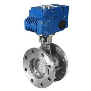
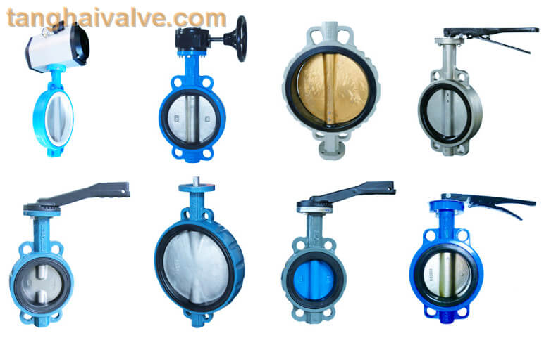
to the structure. According to the sealing form, it is divided into two types: relatively sealed type and hard sealed type. Soft-sealed butterfly valves generally use rubber ring seals, and hard-sealed butterfly valves usually use metal ring seals. According to the connection type, they are divided into flange connection and wafer connection. According to the transmission mode, they are divided into manual, gear transmission, pneumatic, hydraulic and electric. .
Due to the wide variety of butterfly valves, and in special working conditions, the butterfly valve products used are also different. Therefore, for this type of valve, you should choose the type separately from the engineer! According to common types and classifications, butterfly valves can be divided into the following forms:
(1) Classification by structure
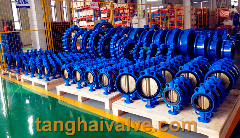
1. Center sealing butterfly valve

Types of wafer butterfly valves

Types of wafer butterfly valves

2. Single eccentric sealing butterfly valve
3. Double eccentric sealing butterfly valve
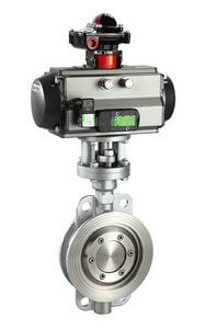
4. Triple eccentric sealing butterfly valve
(2) Classified by link method
1. Wafer butterfly valve
2. Flanged butterfly valve
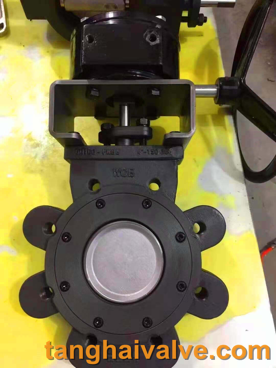
3. Lug butterfly valve
4. Welded butterfly valve
(3) Classified by working temperature
1. High temperature. t>450 °C butterfly valve.
2. Medium temperature butterfly valve. 120 C<t<450 ℃ butterfly valve.
3. Normal temperature butterfly valve. A butterfly valve of 40C<t<120 °C.
4. Low temperature butterfly valve. One 100<t<一40 °C butterfly valve.
(4) Classified by sealing surface material
1. Soft sealing butterfly valve.
(1) The sealing pair is composed of non-metallic soft material to non-metallic soft material.
(2) The sealing pair is composed of metallic hard materials and non-metallic soft materials.
2. Metal hard sealing butterfly valve. The sealing pair is composed of a metal hard material to a metal hard material.
(5) Classified by work pressure
1. Vacuum butterfly valve, a butterfly valve whose working pressure is lower than the atmospheric pressure of the standard stack.
2. Low pressure butterfly valve, butterfly valve with nominal pressure PN<1.6MPa.
3. Medium pressure butterfly valve, butterfly valve with nominal pressure PN of 2.5-6.4MPa.
4. High-pressure butterfly valve, a butterfly valve with a nominal pressure PN of 10.0-80.0MPa.
5. Ultra-high pressure butterfly valve, butterfly valve with nominal pressure PN>100MPa.
(6) Classified by sealing form

Double offset-lug butterfly valve-D372F-150lbC (1)

Double offset-lug butterfly valve-D372F-150lbC (1)

1. Forced sealing butterfly valve.
(1) Elastic sealing butterfly valve. The specific pressure of the seal is generated by the elasticity of the valve seat or the valve plate when the valve plate squeezes the valve seat when it is closed.
(2) External torque sealing butterfly valve. The seal specific pressure is generated by the torque applied to the valve shaft.
2. Pressure-filled and sealed butterfly valve. The specific sealing pressure is generated by the pressure of the elastic sealing element on the valve seat or valve plate.
3. Automatic sealing butterfly valve. The sealing specific pressure is automatically generated by the medium pressure.
Related knowledge: Types of valves Types of regulating valves Types of stop valves Types of ball valves Types of gate valves

TH Valve is a professional manufacturer of butterfly valvegate valvecheck valveglobe valveknife gate valve, ball valve with API, JIS, DIN standard, used in Oil, Gas, Marine industry, Water supply and drainage, fire fighting, shipbuilding, water treatment and other systems, with Nominal Diameter of DN50 to DN1200, NBR/EPDM/VITON, Certificates & Approvals: DNV-GL, Lloyds, DNV, BV, API, ABS, CCS. Standards: EN 593, API609, API6D

Related news /knowledge:
Detailed introduction of soft sealing butterfly valve-(2);
The main classification methods of butterfly valve (1);
Classification of check valves;
Difference between Soft seal gate valve and hard seal gate valve;

Pneumatic gate valve model preparation method

Pneumatic gate valve model preparation method /naming method /code name modification:
Pneumatic gate valve uses compressed air as the power source. Through the up and down movement of the valve stem, the gate is driven to open and close the valve. It has the advantages of reliable performance, convenient

gate valve

gate valve

operation switching and maintenance, and has been widely used by petroleum, chemical, marine and other departments. For the control of various media. For the application of pneumatic gate valves, structural forms, and valve body materials, users should be familiar with the description of the pneumatic gate valve model preparation to avoid problems such as selecting the wrong model, placing the wrong order, and unclear technical parameters causing exchange and return.
Pneumatic gate valve model preparation instructions are mainly for the detailed explanation of the additional conditions of the gate valve, drive mode, connection form, structural feature, sealing material, pressure level and valve body material. Other customized or special product models are not applicable to this method. , Additional explanation is required. To
Pneumatic gate valve model compilation method:
Additional code for gate valve: WZ means bellows gate valve, DZ cryogenic gate valve, NKZ vacuum gate valve, PZ knife gate valve;
Type of gate valve: Z;
Drive mode: manual without code (usually omitted according to regulations), 2 electro-hydraulic, 3 worm gear, 5-bevel gear transmission, 6 pneumatic, 9-electric;
Connection mode: 4 flange connection, 6 welding, 7 pair clip type;
Structural form: 0 elastic gate, 1 open-rod wedge-type single gate, 2-open-rod wedge-type double gate, 3-open-pole parallel single gate, 4-open-pole parallel double gate, 5 concealed Rod wedge single gate, 6 concealed rod wedge double ram, 7 concealed rod parallel single ram, 9 concealed rod parallel double ram;
Sealing material: W valve body is directly processed, T alloy, X rubber, F fluoroplastic, H-Cr stainless steel, Y cemented carbide, M Monel alloy;
Pressure rating: PN1.0-32Mpa, 16=1.6MPA means the pressure is 16 kg, 150LB-1500LB means the American

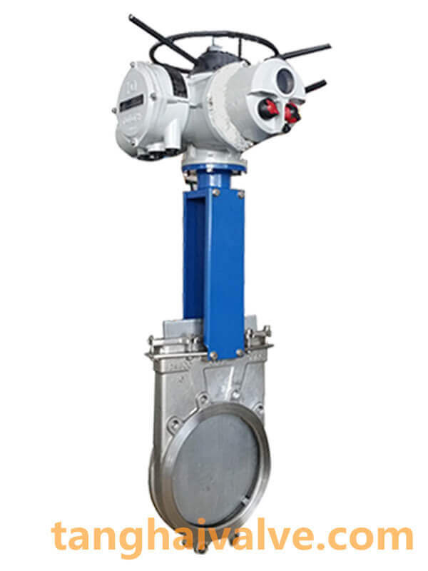
Knife gate valve (1)

Knife gate valve (1)

standard pound pressure, 5-63K means the Japanese pressure;
Valve body material: Z-gray cast iron, Q ductile iron, T alloy, C carbon steel, P stainless steel 304, R stainless steel 316, V chromium molybdenum vanadium steel. gas
Description of the model preparation of the moving gate valve:
PZ673H-10P Stainless steel pneumatic wafer type knife gate valve

1. PZ: stands for knife gate valve;
2. 6: It means that the transmission mode is pneumatic;
3. 7: The connection method is a clip-on connection;
4. 3: The structure is an open pole parallel single gate;
5. H: The sealing material is stainless steel;
6, 10: Indicates that the nominal pressure is 1.0MPa;
7. P: indicates that the valve body material is stainless steel.

TH Valve is a professional manufacturer of butterfly valvegate valvecheck valveglobe valveknife gate valve, ball valve with API, JIS, DIN standard, used in Oil, Gas, Marine industry, Water supply and drainage, fire fighting, shipbuilding, water treatment and other systems, with Nominal Diameter of DN50 to DN1200, NBR/EPDM/VITON, Certificates & Approvals: DNV-GL, Lloyds, DNV, BV, API, ABS, CCS. Standards: EN 593, API609, API6D

Related news /knowledge:
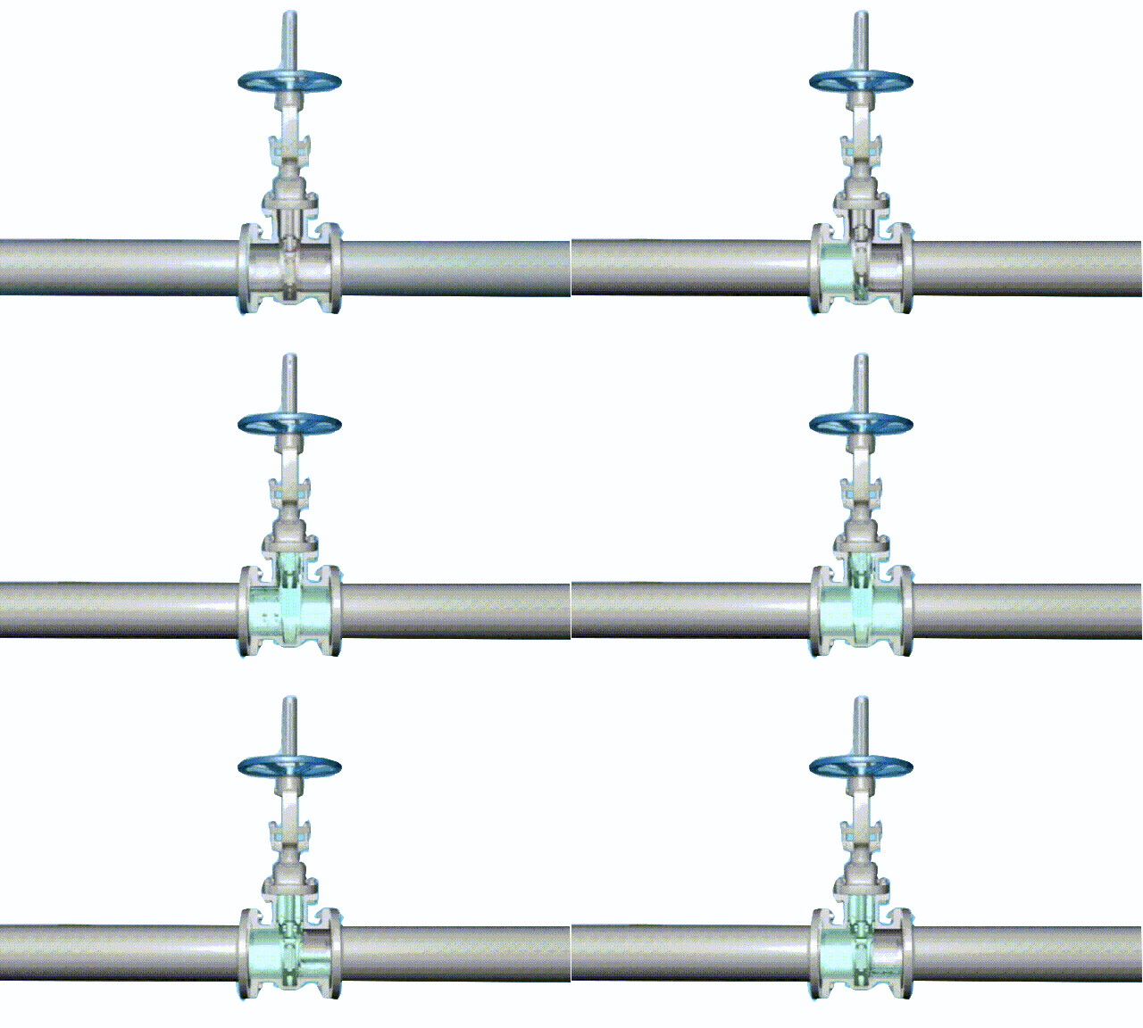
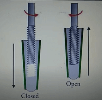
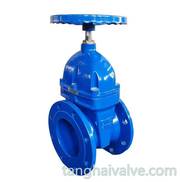
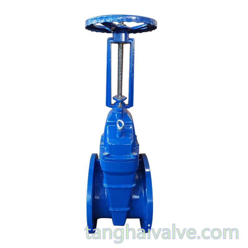
Working principle and movement mode of gate valve;
Valve actuator / actuation -(2)-classification and working principle;
What is the gear modification coefficient;
Representation method of electric gate valve model;

electric wafer butterfly valve vs electric flange butterfly valve

The difference and selection of electric wafer butterfly valve and electric flange butterfly valve
As one of the most common valves in pipelines, electric butterfly valves are used to realize the on-off and flow control of various media in the pipeline system. They have been widely used in many fields such as petroleum, chemical industry, metallurgy, and hydropower. application. Then in the commonly used electric butterfly valve, it can be

D673H-16C-stainless steel pneumatic triple eccentric butterfly valve

D673H-16C-stainless steel pneumatic triple eccentric butterfly valve

divided into two kinds, electric wafer butterfly valve and electric flange butterfly valve, and these two kinds of valves have their own characteristics, and they are not the same in performance. They can be used in Different industries.

For these two kinds of valves, in addition to the different structural forms, if they are under the same parameters, the biggest difference is that the connection method is different, that is, the installation form is different, which depends on the site working conditions!

The difference between electric wafer butterfly valve and electric flange butterfly valve:
The thickness of the electric wafer butterfly valve is relatively thin compared to the flanged butterfly valve. There are no flanges at both ends of the valve body, but only a few guide bolt holes. The valve uses a set of bolts/nuts to connect with the flange of the pipe end, which is generally applicable. It is used in places where the space is relatively narrow or the pipeline is restricted. The advantage is that it is more convenient to disassemble, the valve cost is lower, and the space is small, but the disadvantage is that one sealing surface has a problem, and both sealing surfaces have to be disassembled!
Electric flange butterfly valve has flanges at both ends of the valve body, which are connected with pipeline flanges. Compared with wafer butterfly valves, the sealing performance is more reliable. It is generally used in places with larger diameters or higher pressures, but the cost is relatively good.

D943H-16C-metal seated stainless steel electric triple offset butterfly valve

D943H-16C-metal seated stainless steel electric triple offset butterfly valve

Choice between the two:
However, there are still some things to pay attention to in the design. For example, wafer type valve bolts are generally relatively long. Under high temperature conditions, the expansion of the bolts may cause leakage, so it is not suitable for large pipe diameters under high temperature conditions. . Another example is the wafer butterfly valve generally cannot be used in the end of the pipeline and downstream needs to be disassembled, because when the downstream flange is removed, the wafer valve will fall off, in this case, it must be shortened separately. The flange type butterfly valve does not have the above problems, but the cost will be higher.
Related Electric butterfly valve series products View other butterfly valves

TH Valve is a professional manufacturer of butterfly valvegate valvecheck valveglobe valveknife gate valve, ball valve with API, JIS, DIN standard, used in Oil, Gas, Marine industry, Water supply and drainage, fire fighting, shipbuilding, water treatment and other systems, with Nominal Diameter of DN50 to DN1200, NBR/EPDM/VITON, Certificates & Approvals: DNV-GL, Lloyds, DNV, BV, API, ABS, CCS. Standards: EN 593, API609, API6D

Related news /knowledge:
What is a wafer type butterfly valve;
Wafer type double disc swing check valve introduction;
Comparison and analysis of the performance of the wafer butterfly valve;

Representation method of electric gate valve model

Representation method of electric gate valve model; model name modification method; code name modification method
The electric gate valve is composed of an electric actuator and a gate valve body. The gate plate is controlled by the

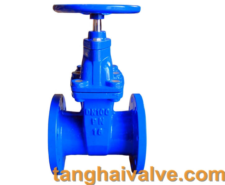
gate valve (1)

gate valve (1)

power supply pressure to perform up and down linear operation to connect or close the fluid medium in the pipeline. The applicable pressure, temperature and caliber range are large, and it is especially suitable for Medium and large diameter pipes. Electric gate valves can be divided into various series. The actuators have on-off type and intelligent type, and the structure is very changeable. When selecting the type, the user should be familiar with the electric gate valve model preparation instructions to avoid selecting the wrong model, placing the wrong order and technology Unknown parameters caused problems such as exchange and return.
Electric gate valve model preparation instructions are mainly for the detailed explanation of the additional conditions of the gate valve, drive mode, connection form, structural feature, sealing material, pressure level and valve body material. Other customized or special product models are not applicable to this method. , Additional explanation is required.
The method of preparing the model of the electric gate valve:
Additional code for gate valve: WZ means bellows gate valve, DZ cryogenic gate valve, NKZ vacuum gate valve, PZ knife gate valve;
Type of gate valve: Z;
Drive mode: manual without code (usually omitted according to regulations), 2 electro-hydraulic, 3 worm gear, 5-bevel gear transmission, 6 pneumatic, 9-electric;
Connection mode: 4 flange connection, 6 welding, 7 pair clip type;
Structural form: 0 elastic gate, 1 open-rod wedge-type single gate, 2-open-rod wedge-type double gate, 3-open-pole parallel single gate, 4-open-pole parallel double gate, 5 concealed Rod wedge single gate, 6 concealed rod wedge double ram, 7 concealed rod parallel single ram, 9 concealed rod parallel double ram;
Sealing material: W valve body is directly processed, T alloy, X rubber, F fluoroplastic, H-Cr stainless steel, Y cemented carbide, M Monel alloy;
Pressure rating: PN1.0-32Mpa, 16=1.6MPA means the pressure is 16 kg, 150LB-1500LB means the American

standard pound pressure, 5-63K means the Japanese pressure;
Valve body material: Z-gray cast iron, Q ductile iron, T alloy, C carbon steel, P stainless steel 304, R stainless steel 316, V chromium molybdenum vanadium steel.

electric stainless steel gate valve

electric stainless steel gate valve

Description of electric gate valve model preparation:
Z941H-16P Stainless steel electric flange gate valve1. Z: represents gate valve;
2. 9: indicates that the transmission mode is electric;
3. 4: The connection method is flange connection;
4. 1: The structure is an open pole wedge single gate;
5. H: The sealing material is stainless steel;
6. 16: Indicates that the nominal pressure is 1.6MPa;
7. P: indicates that the valve body material is stainless steel.

TH Valve is a professional manufacturer of butterfly valvegate valvecheck valveglobe valveknife gate valve, ball valve with API, JIS, DIN standard, used in Oil, Gas, Marine industry, Water supply and drainage, fire fighting, shipbuilding, water treatment and other systems, with Nominal Diameter of DN50 to DN1200, NBR/EPDM/VITON, Certificates & Approvals: DNV-GL, Lloyds, DNV, BV, API, ABS, CCS. Standards: EN 593, API609, API6D

Related news /knowledge:
Representation method of butterfly valve model;
Working principle and movement mode of gate valve; 
Gate valve model meaning and representation method;
Pneumatic gate valve model preparation method;

The sealing characteristics and principle of eccentric butterfly valve

Basic knowledge of eccentric butterfly valve: eccentric butterfly valve, also called offset butterfly valve; Eccentric butterfly valves can be divided into various types, generally single eccentric sealing butterfly valves, double eccentric sealing butterfly valves, and triple eccentric sealing butterfly valves. 
Features of single eccentric sealing butterfly valve:
In order to solve the problem of squeezing between the butterfly plate and the valve seat of the concentric butterfly valve, a single eccentric butterfly valve was produced. Disperse and reduce the excessive squeezing between the upper and lower ends of the butterfly plate and the valve seat. However, because the single eccentric structure does not disappear during the entire opening and closing process of the valve, the scratching phenomenon between the butterfly plate and the valve seat has not disappeared, and the application range is similar to that of the concentric butterfly valve, so it is not used much.

Double eccentric-lug butterfly valve-D72F-150lbP-stainless steel (4)

Double eccentric-lug butterfly valve-D72F-150lbP-stainless steel (4)

The single eccentric sealing butterfly valve has the following characteristics:
1. It has a sealing structure with reliable performance and long service life.
2. It has a truss structure with small flow resistance, good rigidity and small pressure loss.
3. The valve plate sealing ring is easy to replace and easy to maintain.
4. The valve plate sealing ring adopts a “T”-shaped structure, and the sealing pair is linearly sealed.
5. The bottom end of the valve adopts bimetal thrust washer, which has excellent thrust performance.
6. The valve can be installed vertically or horizontally, with good applicability.
7. This type of valve is recommended to be used in one direction, and it can be used in two directions when the reverse sealing requirements are not strict.
8. When the valve is completely closed, the leakage of the seal test is zero.
9. Replace the valve plate sealing ring, O-ring, valve body, valve plate, shaft and other materials, which can be applied to a variety of media and different temperatures.
Features of double eccentric sealing butterfly valve:
On the basis of the single eccentric butterfly valve, the double eccentric butterfly valve is the most widely used double eccentric butterfly valve. Its structural feature is that the axis of the valve stem deviates from the center of the butterfly plate and the center of the body. The double eccentric effect enables the butterfly plate to be released from the valve seat immediately after the valve is opened, which greatly eliminates unnecessary excessive extrusion and scratching of the butterfly plate and the valve seat, reduces the opening resistance, reduces wear and improves The life of the valve seat is improved. The scraping is greatly reduced, and at the same time, the double eccentric butterfly valve can also use a metal seat, which improves the application of the butterfly valve in the high temperature field. But because its sealing principle is a positional sealing structure, that is, the sealing surface of the butterfly plate and the valve seat is in line contact, and the elastic deformation caused by the butterfly plate squeezing the valve seat produces a sealing effect, so the closed position is very demanding (especially metal Valve seat), low pressure bearing capacity, which is why traditionally people think that butterfly valves are not resistant to high pressure and have large leakage.
The main features of the double eccentric butterfly valve are as follows:

1. Adopting full flow design, not affected by impurity jamming. The conjoined “O”-shaped sealing line at both ends makes the pipeline installation without gaskets and maintains a reliable seal. Different materials can be selected according to different usage requirements.
2. The butterfly plate material adopts streamlined design, which can be used in two directions, with low flow resistance and excellent flow characteristics.
3. The shaft pin adopts the unpinning structure, which can tightly combine the butterfly valve stems without weakening the strength of the shaft and has good interchangeability.
4. The valve body connection can be applied to ANSI125/150, DIN2501 PN10/16, JISB2210 10K, JIS G5527 7.5K standards.
Features of triple eccentric sealing butterfly valve:

triple offset butterfly valve-double flange- (4)

triple offset butterfly valve-double flange- (4)

1. API specifications
2. Double safety structure
3. No dead zone design
4. Body valve seat structure
5. Thin layer valve seat structure
6. Replaceable seal pair
7. Balanced fixed structure
8. Intrinsic refractory structure
9. High sealing packing structure
The structural feature of the triple eccentric butterfly valve is that while the double eccentric valve stem axis position is eccentric, the conical axis of the butterfly plate sealing surface is skewed to the cylinder axis of the body, that is to say, after the third eccentricity, the butterfly plate seals The cross-section is no longer a true circle, but an ellipse, and the shape of the sealing surface is therefore asymmetrical. One side is inclined to the center line of the body, and the other side is parallel to the center line of the body. The biggest feature of this third eccentricity is that the sealing structure is fundamentally changed. It is no longer a positional seal, but a torsion seal, that is, it does not rely on the elastic deformation of the valve seat, but completely relies on the contact surface pressure of the valve seat to achieve the seal. Therefore, the problem of zero leakage of the metal valve seat is solved in one fell swoop, and because the contact surface pressure is proportional to the medium pressure, the high pressure and high temperature resistance is also solved. Since its inception, the triple eccentric butterfly valve itself has undergone a process of self-improvement and continuous development in order to meet the increasingly severe requirements of working conditions. Even if the highest zero leakage is required, the triple eccentric butterfly valve can theoretically be achieved, but in fact it still relies on careful design and precision manufacturing.
Related knowledge: features of eccentric butterfly valve; Installation instructions of double eccentric butterfly valve

Related products: Electric triple eccentric butterfly valve Pneumatic triple eccentric butterfly valve

TH Valve is a professional manufacturer of butterfly valvegate valvecheck valveglobe valveknife gate valve, ball valve with API, JIS, DIN standard, used in Oil, Gas, Marine industry, Water supply and drainage, fire fighting, shipbuilding, water treatment and other systems, with Nominal Diameter of DN50 to DN1200, NBR/EPDM/VITON, Certificates & Approvals: DNV-GL, Lloyds, DNV, BV, API, ABS, CCS. Standards: EN 593, API609, API6D

Butterfly valve use principle and installation instructions

Butterfly valve use principle and installation instructions
The relationship between the opening of the butterfly valve and the flow rate basically changes linearly. If it is used to control flow, its flow characteristics are also closely related to the flow resistance of the piping. For example, two pipelines are installed with the same valve diameter and form, but the pipeline loss coefficient is different, and the flow rate of the valve will also be very different.

butterfly valve working diagram-3D GIF animated presentation

butterfly valve working diagram-3D GIF animated presentation

If the valve is in a state with a large throttle range, the back of the valve plate is prone to cavitation, which may damage the valve. Generally, it is used outside 15°. When the butterfly valve is in the middle opening degree, the opening shape formed by the valve body and the front end of the butterfly plate is centered on the valve shaft, and the two sides form different states. Therefore, one side of the valve body and the valve plate form a nozzle-like opening, and the other side is similar to a throttle opening. The nozzle side has a much faster flow rate than the throttle side, and negative pressure will be generated under the throttle side valve. The rubber seal may fall off.

The operating torque of the butterfly valve has different values ​​due to the different opening and closing directions of the valve. The horizontal butterfly valve, especially the large-diameter valve, due to the depth of water, the torque produced by the difference between the upper and lower water heads of the valve shaft cannot be ignored. In addition, when an elbow is installed on the inlet side of the valve, a bias flow is formed and the torque will increase. When the valve is in the middle opening, the operating mechanism needs to be self-locking due to the action of the water flow torque.

ductile iron, DI, butterfly valve, manufacturer, center line, TH valve

ductile iron, DI, butterfly valve, manufacturer, center line, TH valve

TH Valve is a professional manufacturer of butterfly valvegate valvecheck valveglobe valveknife gate valve, ball valve with API, JIS, DIN standard, used in Oil, Gas, Marine industry, Water supply and drainage, fire fighting, shipbuilding, water treatment and other systems, with Nominal Diameter of DN50 to DN1200, NBR/EPDM/VITON, Certificates & Approvals: DNV-GL, Lloyds, DNV, BV, API, ABS, CCS. Standards: EN 593, API609, API6D

Related news /products:
Butterfly valve and its Development history – (1)
Working principle diagram of swing check valve;
Valve actuator / actuation -(3)-classifications;
Installation instructions of double eccentric butterfly valve;

Gate valve model meaning and representation method

Gate valve model representation method | Gate valve model meaning
Explanation of the meaning of the gate valve model:

pneumatic gate valve (3)

pneumatic gate valve (3)

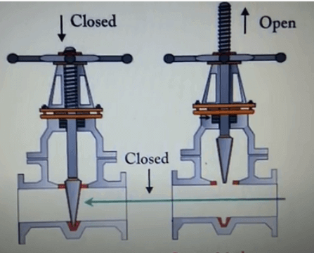
Gate valve is one of the more common types of shut-off valves. It is generally suitable for full-open or full-close two-position operation control. It is mainly used to close the medium in the pipeline. It is usually called a cut-off valve or a blocking valve. With the increase in demand for valves and the expansion of demand in the machinery industry, gate valves have become an indispensable part of modern industrial control systems. For more and more complex working conditions and harsh use requirements, the correct selection of gate valve models is related to the adaptability of the pipeline medium and an important guarantee for the safety of the working conditions. The user should have a detailed understanding of the method of preparing the gate valve model to avoid problems such as selecting the wrong model, placing the wrong order, and unclear technical parameters resulting in replacement and return.
This compilation method is the representation method of the standard gate valve model in my country. It mainly explains in detail the additional conditions of the gate valve, drive mode, connection form, structural feature, sealing material, pressure level and valve body material. Other customized or special product models are not applicable to this method and need to be explained separately.
The method of formulating and expressing gate valve model:
Additional code for gate valve: WZ means bellows gate valve, DZ cryogenic gate valve, NKZ vacuum gate valve, PZ knife gate valve;
Type of gate valve: Z;
Drive mode: manual without code (usually omitted according to regulations), 2 electro-hydraulic, 3 worm gear, 5-bevel gear transmission, 6 pneumatic, 9-electric;
Connection mode: 4 flange connection, 6 welding, 7 pair clip type;
Structural form: 0 elastic gate, 1 open-rod wedge-type single gate, 2-open-rod wedge-type double gate, 3-open-pole parallel single gate, 4-open-pole parallel double gate, 5 concealed Rod wedge single gate, 6 concealed rod wedge double ram, 7 concealed rod parallel single ram, 9 concealed rod parallel double ram;
Sealing material: W valve body is directly processed, T alloy, X rubber, F fluoroplastic, H-Cr stainless steel, Y cemented carbide, M Monel alloy;
Pressure rating: PN1.0-32Mpa, 16=1.6MPA means the pressure is 16 kg, 150LB-1500LB means the American standard pound pressure, 5-63K means the Japanese pressure;
Valve body material: Z-gray cast iron, Q ductile iron, T alloy, C carbon steel, P stainless steel 304, R stainless steel 316, V chromium molybdenum vanadium steel.

Knife-gate-valve-1-

Knife-gate-valve-1-

Example of preparing gate valve model:
PZ973H-16C Electric Wafer Type Knife Gate Valve

1. PZ: stands for knife gate valve;
2. 9: indicates that the transmission mode is electric;
3. 7: The connection method is a clip-on connection;
4. 3: The structure is an open pole parallel single gate;
5. H: The sealing material is stainless steel;
6. 16: Indicates that the nominal pressure is 1.6MPa;
7. C: Indicates that the valve body material is carbon steel.

TH Valve is a professional manufacturer of butterfly valvegate valvecheck valveglobe valveknife gate valve, ball valve with API, JIS, DIN standard, used in Oil, Gas, Marine industry, Water supply and drainage, fire fighting, shipbuilding, water treatment and other systems, with Nominal Diameter of DN50 to DN1200, NBR/EPDM/VITON, Certificates & Approvals: DNV-GL, Lloyds, DNV, BV, API, ABS, CCS. Standards: EN 593, API609, API6D

related news /knowledge:
Representation method of butterfly valve model;
Representation method of electric gate valve model;
Pneumatic gate valve model preparation method;

Butterfly valve structure principle and application analysis

Butterfly valve (also called flap valve) is a kind of regulating valve whose closing part is circular disc or disc, mainly composed of valve body, valve stem, disc and sealing ring. The valve body is cylindrical with short axial length and built-in butterfly plate. The butterfly plate of the butterfly valve is installed in the diameter direction of the pipeline. In the cylindrical passage of the butterfly valve body, the disc-shaped butterfly plate rotates around the axis, and the rotation angle is between 0° and 90°. When the rotation reaches 90°, the valve is fully opened.

Double offset-flanged butterfly valve-D42F-150lbC (1)

Double offset-flanged butterfly valve-D42F-150lbC (1)

The butterfly valve is simple in structure, small in size and light in weight, and consists of only a few parts. Moreover, it can be opened and closed quickly by rotating 90°, and the operation is simple. At the same time, the valve has good fluid control characteristics. When the butterfly valve is in the fully open position, the thickness of the butterfly plate is the only resistance when the medium flows through the valve body, so the pressure drop generated by the valve is small, so it has better flow control characteristics. The butterfly valve has two sealing types: elastic seal and metal seal. Elastic sealing valve, the sealing ring can be inlaid on the valve body or attached to the periphery of the butterfly plate.
Butterfly valves with metal seals generally have a longer life than those with elastic seals, but it is difficult to achieve a complete seal. The metal sealing butterfly valve can adapt to higher working temperature, while the elastic sealing butterfly valve has the defect of being limited by temperature.
If the butterfly valve is required to be used as a flow control, the main thing is to correctly select the size and type of the valve. The structure principle of butterfly valve is especially suitable for making large-diameter valves. Butterfly valves are not only widely used in general industries such as petroleum, gas, chemical, and water treatment, but also used in cooling water systems of thermal power stations.

Double eccentric-lug butterfly valve-D72F-150lbP-stainless steel (4)

Double eccentric-lug butterfly valve-D72F-150lbP-stainless steel (4)

Commonly used butterfly valves include wafer type butterfly valves and flange type butterfly valves. Wafer type butterfly valve uses double-head bolts to connect the valve between two pipe flanges. Flange type butterfly valve has flanges on the valve, and bolts are used to connect the flanges at both ends of the valve to the pipe flanges.

TH Valve is a professional manufacturer of butterfly valvegate valvecheck valveglobe valveknife gate valve, ball valve with API, JIS, DIN standard, used in Oil, Gas, Marine industry, Water supply and drainage, fire fighting, shipbuilding, water treatment and other systems, with Nominal Diameter of DN50 to DN1200, NBR/EPDM/VITON, Certificates & Approvals: DNV-GL, Lloyds, DNV, BV, API, ABS, CCS. Standards: EN 593, API609, API6D

Related news /products:
What is a wafer type butterfly valve;
The working principle of butterfly valve (picture);
What is the material of the main parts of the butterfly valve?-(2)
Notes on selection and installation of butterfly valve;

Principle of Globe Valve (Figure)

Globe Valve is also called stop valve, shut-off valve. The opening and closing part of the globe valve is a plug-shaped valve disc, the sealing surface is flat or cone, and the valve disc moves linearly along the centerline of the fluid. The movement form of the valve stem includes a lifting rod type (the valve stem is raised and lowered, the hand wheel does not lift), and there is a lifting rotating rod type (the hand wheel and the valve stem rotate and lift together, and the nut is set on the valve body). The stop valve is only suitable for fully open and fully closed, adjustment and throttling are not allowed.
Brief introduction to the principle of the globe valve:

globe cut-off valve working diagram-3D GIF animated presentation

globe cut-off valve working diagram-3D GIF animated presentation

To put it simply, the principle of the globe valve is to use the torsion of the valve stem to give a downward pressure on the sealing surface, and rely on the pressure of the valve stem to make the disc sealing surface and the valve seat sealing surface closely fit to prevent the inflow of the medium or adjust the flow rate of the medium. . The opening and closing part of the stop valve is a cylindrical valve disc, the sealing surface is flat or conical, and the valve disc moves linearly along the center line of the fluid. The movement mode of the valve stem includes a lifting rod type (the valve stem is raised and lowered, and the hand wheel does not lift), and there is also a lifting rotating rod type

Schematic diagram of shut-off valve (closed state)

Schematic diagram of shut-off valve (closed state)

(the hand wheel and the valve stem rotate and lift together, and the nut is set on the valve body). The globe valve is a forced sealing valve, so when the valve is closed, pressure must be applied to the disc to force the sealing surface to not leak.

The working principle of the stop valve:
We assume that there is a pipe with a lid. Water flows in from the bottom of the pipe and flows out toward the nozzle. The lid of the outlet pipe is equivalent to the closing part of the shut-off valve. If the pipe lid is lifted up by hand, the water will flow out. When the cap is closed, the water stops flowing, which is equivalent to the working principle of a shut-off valve.

The shut-off valve relies on rotating the hand wheel to make the valve stem rise and fall, and drive the valve disc to make a linear displacement parallel to the flow direction of the medium to achieve the purpose of opening and closing. The handwheel rotates in a clockwise direction, and the working medium enters from the channel under the valve disc. At this time, the applied sealing force must be equal to or greater than the sum of the required specific pressure generated on the sealing surface and the upward force of the medium.

Schematic diagram of shut-off valve (open state)

Schematic diagram of shut-off valve (open state)

Schematic diagram of shut-off valve (open state)

When the shut-off valve is opened, when the opening height of the disc is 25% to 30% of the nominal diameter, the flow has reached the maximum, indicating that the valve has reached the fully open position. Therefore, the fully open position of the shut-off valve should be determined by the stroke of the valve disc.
Note:
1. The shut-off valve only allows the medium to flow in one direction, and has directionality when installed. ,
2. The function of the shut-off valve is either 0 or 1, either through or not through. In other words, the shut-off valve is only suitable for fully open and fully closed, and adjustment and throttling are not recommended.

TH Valve is a professional manufacturer of butterfly valvegate valvecheck valveglobe valveknife gate valve, ball valve with API, JIS, DIN standard, used in Oil, Gas, Marine industry, Water supply and drainage, fire fighting, shipbuilding, water treatment and other systems, with Nominal Diameter of DN50 to DN1200, NBR/EPDM/VITON, Certificates & Approvals: DNV-GL, Lloyds, DNV, BV, API, ABS, CCS. Standards: EN 593, API609, API6D

Related knowledge:
The working principle and characteristics of the globe valve;
Electric globe valve selection and application;
The working principle of butterfly valve (picture);

The difference between a float valve and a ball valve

The difference between a float valve and a ball valve, the principle of the float valve | diagram
Float valve is a product of liquid level measurement and control. It is constructed by several main components such as valve body, piston, connecting rod and floating ball, and uses the principle of leverage to make the valve open or block. In the simplest way, it is like a flush toilet at home, and the water supply device used on it has this structure.
The difference between float valve and ball valve:

electric ball valve

electric ball valve

The ball valve is a kind of valve, which refers to the valve core (sealing part) of the valve with a spherical structure, which is used in the pipeline to block air or water flow; the float valve is because one end of the switch lever is a hollow sealing ball, Automatically control the opening and closing of the valve through the buoyancy of the liquid. One word difference is very different.

The working principle of the float valve|Illustration:
The float valve floats must always float on the water. When the water surface rises, the float also rises. When the

principle of the float valve diagram

principle of the float valve diagram

water level of the water tank is low, the floating ball decreases with the water level, and the piston in the valve body is pulled out through the connecting rod of the fixed floating ball, so that the valve body and the piston are hollowed out, so that the tap water can enter the water tank; when the water level of the water tank is set When the height position is high, the force generated by the floating ball as the water level rises pushes the piston in the valve body into the valve body through the connecting rod. Because the top of the piston is equipped with a sealing rubber gasket, the water outlet in the valve body is processed relatively flat and smooth. When the buoyancy of the floating ball exceeds the pressure of the tap water, the piston with the sealing rubber gasket and the water outlet in the valve body are tightly sealed, and the tap water is closed by the floating ball valve.
Floating ball valve function: control the water level of the pool or water tank not to exceed a certain set value, and the valve can only be opened within a set time period. Floating ball valve is applicable: used in the reservoir system of the tap water supply pipe network to avoid opening the reservoir inlet valve during peak water consumption and reduce the pressure of the water supply pipe network. The valve can only open when the water is low.
Click to view: Principle of Ball Valve Principle of Electric Ball Valve Principle of Pneumatic Ball Valve

TH Valve is a professional manufacturer of butterfly valvegate valvecheck valveglobe valveknife gate valve, ball valve with API, JIS, DIN standard, used in Oil, Gas, Marine industry, Water supply and drainage, fire fighting, shipbuilding, water treatment and other systems, with Nominal Diameter of DN50 to DN1200, NBR/EPDM/VITON, Certificates & Approvals: DNV-GL, Lloyds, DNV, BV, API, ABS, CCS. Standards: EN 593, API609, API6D

Related news /Products:
The role and use of the ball valve;
Types and classifications of ball valves;
The difference between fixed ball valve and floating ball valve
Working Principle of Pneumatic Gate Valve;