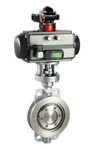
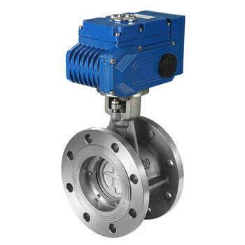
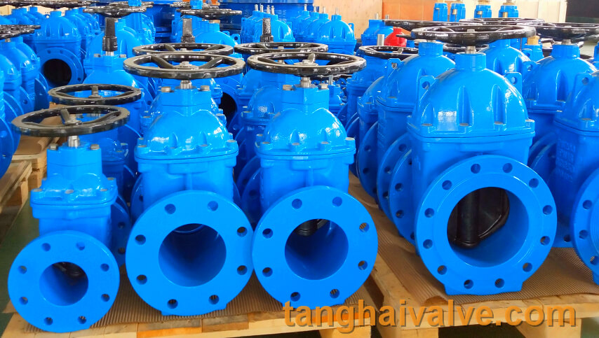
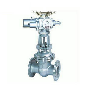
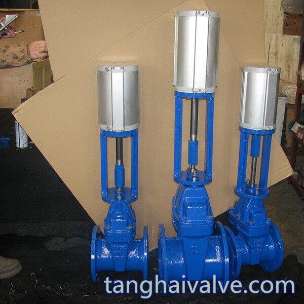
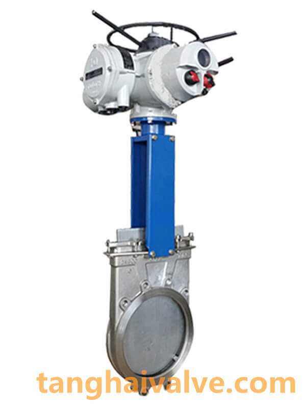
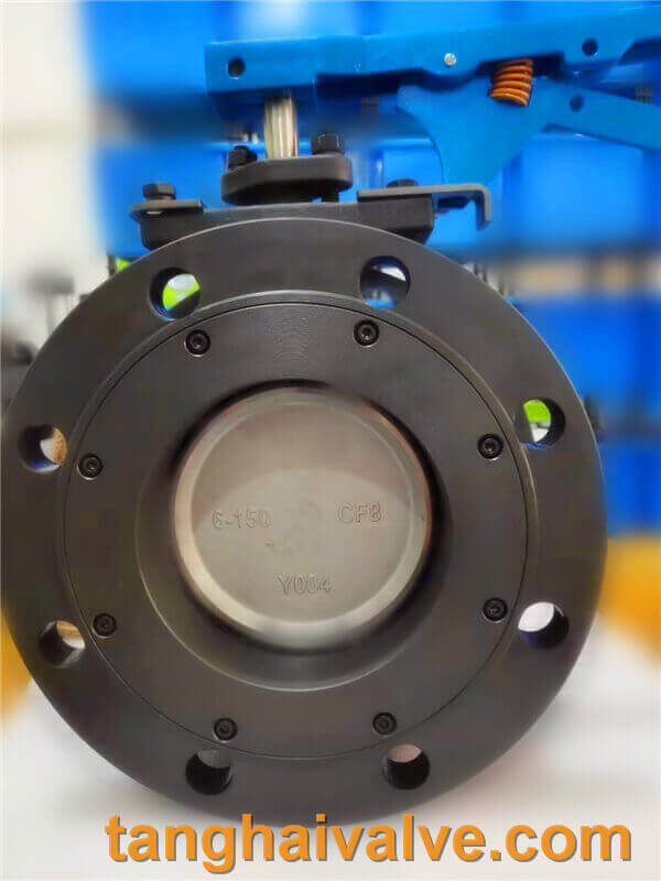
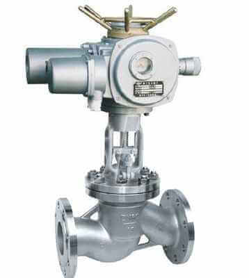
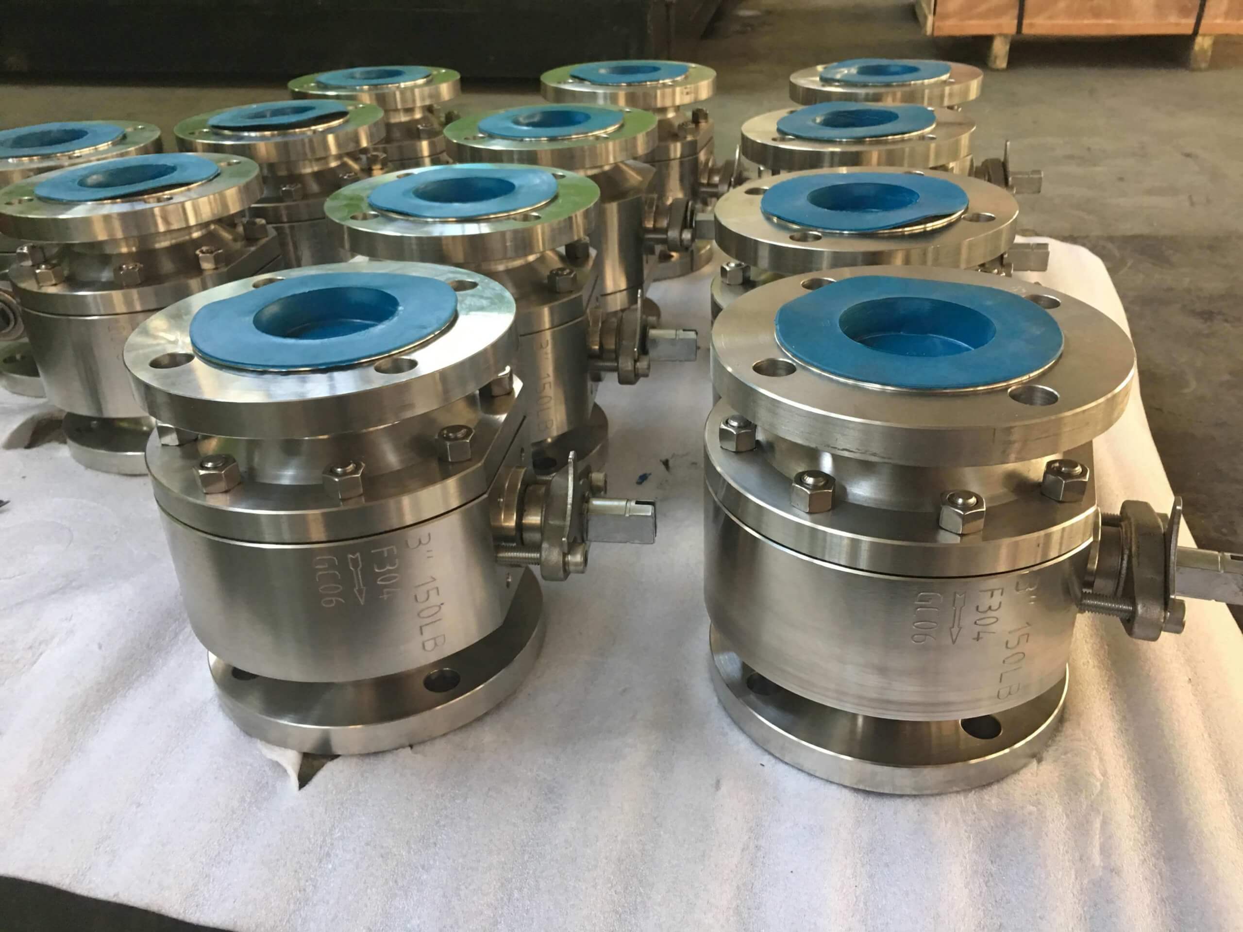
Electric globe valve selection and application

Electric shut-off valve selection, Electric shut-off valve application, globe valve also named shut off valve or cut off valve.
Advantages of electric shut-off valve:
Once the electric shut-off valve is in the open state, there is no contact between its valve seat and the sealing surface of the disc, so its sealing surface is less mechanically worn, because most of the electric shut-off valves have relatively easy repairs. Or there is no need to remove the entire valve from the pipeline when replacing the sealing

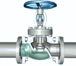
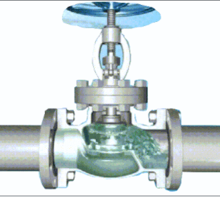
electric globe valve

electric globe valve

element,which is very suitable for the occasion where the valve and the pipeline are welded together. The most obvious advantage is that during the opening and closing process, the friction between the disc and the sealing surface of the valve body is smaller than that of the gate valve, so it is wear-resistant. The opening height is generally only 1/4 of the diameter of the valve seat passage, so it is much smaller than the gate valve. Usually there is only one sealing surface on the valve body and the valve flap, so the manufacturing process is better and it is easy to maintain. The flow direction of the medium through this type of valve has changed, so the flow resistance of the electric shut-off valve is higher than that of other valves.

Selection of electric shut-off valve:
Commonly used electric globe valves are electric straight-through globe valves, electric throttle valves, electric angle globe valves, electric DC globe valves, electric plunger globe valves, etc. In addition to electric throttle valves, other electric globe valves generally do not Make high-pressure choices.
1. Angle type electric shut-off valve; in the angle type electric shut-off valve, the fluid only needs to change its direction once, so that the pressure drop through this valve is smaller than that of the conventional structure of the electric shut-off valve.
2. DC type electric shut-off valve; electric shut-off valve in the DC type or Y-shaped electric shut-off valve, the flow passage of the valve body is in a diagonal line with the main flow path, so that the degree of damage to the flow state is smaller than that of the conventional electric shut-off valve, so it passes The pressure loss of the valve is correspondingly small.
3. Plunger type electric shut-off valve: This type of electric shut-off valve is a modification of the conventional electric shut-off valve. In this valve, the disc and valve seat are usually designed based on the plunger principle. The valve clack is polished so that the plunger and the valve stem are connected, and the sealing is achieved by two elastic sealing rings sleeved on the plunger. The two elastic sealing rings are separated by a sleeve ring, and the sealing ring around the plunger is pressed firmly by the load exerted on the bonnet by the bonnet nut.
Electric shut-off valve application:
If the electric shut-off valve is used in high-pressure occasions, it is generally connected by butt welding, or electric angle type shut-off valve is used. According to the material, you can choose carbon steel or 304 stainless steel. If the temperature is relatively high, you need to choose chromium-molybdenum steel or chromium-molybdenum-vanadium steel. The typical J941Y-170V electric high temperature and high pressure stop valve used in power plants.

TH Valve is a professional manufacturer of butterfly valvegate valvecheck valveglobe valveknife gate valve, ball valve with API, JIS, DIN standard, used in Oil, Gas, Marine industry, Water supply and drainage, fire fighting, shipbuilding, water treatment and other systems, with Nominal Diameter of DN50 to DN1200, NBR/EPDM/VITON, Certificates & Approvals: DNV-GL, Lloyds, DNV, BV, API, ABS, CCS. Standards: EN 593, API609, API6D

Related news /knowledge:
Classification of the globe valves-(1);
The working principle and characteristics of the globe valve;
Electric globe valve model coding method.
working principle of electric globe valve

Ball valve installation and maintenance methods

Ball valve installation:
1. It must be confirmed that the pipeline and valve have been cleaned before operation.
2. The actuator operation of the valve drives the valve stem to complete rotation according to the size of the input signal: when it rotates 1/4 turn (900) in the forward direction, the valve is closed. When the reverse rotation is 1/4 turn (900), the valve opens.

fixed ball valve

fixed ball valve

3. When the direction indicator arrow of the actuator is parallel to the pipeline, the valve opens; when the arrow is perpendicular to the pipeline, the valve closes.
Ball valve repair:
Longer service life and maintenance-free time will depend on several factors: under normal working conditions, maintaining a harmonious temperature/pressure ratio, and reasonable corrosion data. Note: When the ball valve is closed, the fluid pressure in the valve body It still exists. Before maintenance, remove the pipeline pressure and leave the valve in the open position. Before maintenance, disconnect the power supply or air supply. Before maintenance, disconnect the actuator from the bracket.

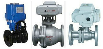
electric ball valve

electric ball valve

1. Packing lock If the packing culvert is slightly leaking, the valve stem nut must be locked. Note: Do not lock, usually lock 1/4 ring to 1 ring, the leakage will stop.
2. Replace the valve seat and seal
A. Disassembly Keep the valve in the half-open position to flush out the dangerous substances that may exist inside and outside the valve. Close the ball valve, remove the bolts and nuts of the flanges on both sides, and completely remove the valve from the pipeline. Disassemble the drive device-actuator, connecting bracket, lock washer, stem nut, butterfly shrapnel, glam, wear-resistant sheet, stem packing in order. Remove the body cover connecting bolts and nuts, separate the valve cover from the valve body, and remove the valve cover gasket. Make sure that the valve ball is in the “off” position. This will make it easier to take it out of the valve body, and then remove the valve seat. Gently push the valve stem down from the hole in the valve body until it is completely taken out, and then take out the O-ring and packing ring. Note: Please operate carefully to avoid scratching the surface of the valve stem and the packing seal of the valve.
B. Reassembly Clean and inspect the parts under investigation. It is strongly recommended to replace the valve seat and bonnet gaskets and seals with spare parts kits. Reverse the order of disassembly and assembly. Use the specified torque to tighten the flange bolts crosswise. Tighten the nut with the specified torque. After installing the actuator, rotate the valve stem to drive the valve core to rotate the corresponding input signal to make the valve open and close. If possible, after installing the pipeline, test the sealing pressure and performance of the valve according to the standard.
Related knowledge: The role of the ball valve The working principle of the ball valve

TH Valve is a professional manufacturer of butterfly valvegate valvecheck valveglobe valveknife gate valve, ball valve with API, JIS, DIN standard, used in Oil, Gas, Marine industry, Water supply and drainage, fire fighting, shipbuilding, water treatment and other systems, with Nominal Diameter of DN50 to DN1200, NBR/EPDM/VITON, Certificates & Approvals: DNV-GL, Lloyds, DNV, BV, API, ABS, CCS. Standards: EN 593, API609, API6D

Related news /knowledge:
Electric flange ball valve installation instructions;
Installation and maintenance of electric ball valve; 
Installation and maintenance of electric ball valve;
Valves’ sealing requirements and daily maintenance;

The role and use of the ball valve

The function of the ball valve:
The opening and closing part of the ball valve is a round sphere with a hole. The ball core rotates around the axis of the valve stem by 0-90° back and forth to achieve the purpose of opening or closing the valve. Ball valves have many functions. They are generally used to switch off or adjust the medium in the pipeline. Among them, the three-way ball valve can flexibly cut off, distribute and change the flow direction of the medium. The sealing surface of the ball valve is usually closed with the spherical surface, so it is not easy to be eroded by the medium. It is easy to operate and has a simple and compact structure. It can be used in working conditions such as water, natural gas, acid, and solvent.

fixed ball valve

fixed ball valve

The application of the ball valve:
Ball valves can generally be divided into three categories: floating ball valves, fixed ball valves, and elastic ball valves according to their structure. According to the different sealing performance, it is divided into hard-sealed ball valves and soft-sealed ball valves. The soft-sealed ball valves have better sealing performance and can achieve zero leakage. They are generally used in normal temperature and pressure pipelines with corrosive media, while hard-sealed ball valves are not only It can be used in normal temperature and pressure, as well as pipelines with low temperature and low pressure and high temperature and high pressure.
(1) Floating ball valve
The ball of the floating ball valve is floating and is supported by two valve seats. Under the action of the medium pressure, the ball can produce a certain displacement and tightly adhere to the sealing surface of the valve seat at the outlet end to ensure that the outlet end is sealed. However, if the sphere bears the load of the working medium and is all transmitted to the outlet sealing ring, the sphere may deviate when it is impacted by a higher pressure. Therefore, the ball valve of this structure is generally suitable for normal pressure or low pressure working conditions.
(2) Fixed ball valve

Pneumatic electric high platform ball valve

Pneumatic electric high platform ball valve

The name of the fixed ball valve is that the ball is fixed, and when the valve is closed, the ball valve will not move even if it is pressurized. Fixed ball valves are equipped with a floating seat. After being pressured by the medium, the seat will move so that the sealing ring is pressed tightly on the sphere to ensure sealing. Generally, sliding bearings or rolling bearings are installed on the upper and lower shafts of the ball, which can be operated with a small torque and a small torque, and is generally suitable for high-pressure and large-diameter pipelines.
Other common classifications of ball valves, chip ball valves, orbital ball valves, V-shaped ball valves, O-shaped ball valves, cut-off ball valves, three-way ball valves, four-way ball valves, forged steel ball valves, ash unloading ball valves, anti-sulfur ball valves, eccentric ball valves, thermal insulation ball valves, pneumatic Ball valves, electric ball valves, ferrule ball valves, welded ball valves. Among them, the V-shaped ball valve has a shearing effect, which is especially suitable for media containing fibers, small solid particles, slurry and other media. The three-way ball valve can also be divided into T-type and L-type. The T-shape can make the three intersecting pipelines connect to each other or cut off any one of the channels, playing the role of splitting and merging. The L-shape only connects two perpendicular pipes, and cannot connect to the third pipe at the same time, and it mainly plays a role of distribution.
Related knowledge: working principle of ball valve structure diagram of ball valve.

TH Valve is a professional manufacturer of butterfly valvegate valvecheck valveglobe valveknife gate valve, ball valve with API, JIS, DIN standard, used in Oil, Gas, Marine industry, Water supply and drainage, fire fighting, shipbuilding, water treatment and other systems, with Nominal Diameter of DN50 to DN1200, NBR/EPDM/VITON, Certificates & Approvals: DNV-GL, Lloyds, DNV, BV, API, ABS, CCS. Standards: EN 593, API609, API6D

Types and classifications of globe valve

Type of globe valve / Classification of globe valve
The globe valve, also called the shut off valve or cut-off valve, is the most widely used valve, which is mainly composed of a valve body, a valve clack, a valve cover, and a valve stem. The valve body and valve cover are pressure-bearing parts, and the valve clack and valve stem are internal parts. The shut-off valve is a valve in which the closing part (disc) moves along the center line of the valve seat. According to this movement form of the valve disc, the change of the valve seat port is proportional to the valve disc stroke.

Classification of stop valves:
According to the structure of the valve body, the globe valve is divided into right-angle type, straight-through type and direct-flow type.
1. The right-angle fluid only needs to change its direction once, so that the pressure drop through this valve is smaller

than that of a conventional shut-off valve. The valve body is mostly forged, which is suitable for shut-off valves with smaller passages and higher pressures.

Globe valve (2)

right-angle Globe valve (2)

2. The straight-through type is the most common structure. The medium inlet and outlet channels are 180° in the same direction, but the fluid resistance is the largest.

Globe valve (9)

straight-through Globe valve (9)

3. In the direct-flow or Y-shaped stop valve, the flow channel of the valve body is in an oblique line with the main flow channel, and the fluid resistance is small. It is mostly used for fluids containing solid particles or high viscosity.

Globe valve (1)

Y-shaped Globe valve (1)

Type of stop valve:
According to nominal pressure: vacuum, low pressure, medium pressure, high pressure, ultra high pressure valve, etc.;
According to working temperature: high temperature, medium temperature, normal temperature, low temperature, ultra-low temperature valve, etc.;

According to the driving mode: manual valve, power driven valve (electromagnetic, pneumatic, hydraulic, electric and various linkage valves), automatic valve, etc.;
According to the valve body material: cast iron, cast copper, cast steel, carbon steel, titanium, stainless steel valves, etc.;
By application sector: general purpose valves, power station valves, marine valves, metallurgical valves, pipeline valves, plumbing valves, etc.;
According to the structure: straight-through type, angle type, direct current type, etc.;
According to the connection form: internal thread, external thread, flange, welding,

clamp, clamp, ferrule, etc.;

TH Valve is a professional manufacturer of butterfly valvegate valvecheck valveglobe valveknife gate valve, ball valve with API, JIS, DIN standard, used in Oil, Gas, Marine industry, Water supply and drainage, fire fighting, shipbuilding, water treatment and other systems, with Nominal Diameter of DN50 to DN1200, NBR/EPDM/VITON, Certificates & Approvals: DNV-GL, Lloyds, DNV, BV, API, ABS, CCS. Standards: EN 593, API609, API6D

Related news /knowledge:
Pneumatic globe valve model preparation method;
Characteristics and working principle of electric globe valve;
The working principle and characteristics of the globe valve;
The difference between globe valve and check valve

Electric ball valve-metal seated vs soft-seated type

What is the difference between an electric hard-sealed ball valve and an electric soft-sealed ball valve?
There are many types of ball valves, and the corresponding working conditions are different according to the structure, connection method and valve body material. However, in all types of ball valves, the sealing form is only divided into two categories: soft seal and hard seal. Since the sealing materials used are different, the performance characteristics of the products are different, so the applicable working conditions are naturally different.

electric ball valve

electric ball valve

1. From the price point of view, compared with the electric hard-sealed ball valve, the price of the electric soft-sealed ball valve will be cheaper and the cost will be lower!
2. In terms of material, electric hard-sealed ball valves use metal seats, mostly stainless steel + cemented carbide, with high machining accuracy and process technology requirements, and a wide range of applications. They can be used in normal temperature, low temperature, and high temperature and high pressure conditions. Electric soft-sealed ball valve, the valve seat is divided into fluoroplastics, rubber, resin and other types, mostly used in normal pressure and normal temperature, normal pressure and low temperature conditions.

3. From the structural mechanism
(1) The electric soft sealing ball valve is easy to achieve better sealing effect, and is resistant to corrosion, acid and alkali; the disadvantage is that it is not resistant to high temperatures, the sealing surface is easy to wear, and the mechanical properties are relatively poor. (Used for occasions with high sealing requirements, or corrosive media, and no particles at room temperature and pressure.)
(2) Electric hard-sealed ball valve is the opposite, which can withstand high temperature, abrasion resistance, and has good mechanical properties. The disadvantage is that the sealing performance of this type of seal is poor. (Generally, it is recommended to use hard-sealed ball valves for media that contain solid particles or wear and whose temperature is higher than 250 degrees.)
4. From the level of valve leakage, hard-sealed valves: Generally, they are Class V, and can reach Class VI as high as possible. Soft-seal valve: generally VI grade. The biggest problem with soft-seal valves is poor wear resistance. After using for a period of time, if there are solid impurities in the liquid medium, the valve seat may be worn, which will increase the leakage and decrease the sealing performance.

TH Valve is a professional manufacturer of butterfly valvegate valvecheck valveglobe valveknife gate valve, ball valve with API, JIS, DIN standard, used in Oil, Gas, Marine industry, Water supply and drainage, fire fighting, shipbuilding, water treatment and other systems, with Nominal Diameter of DN50 to DN1200, NBR/EPDM/VITON, Certificates & Approvals: DNV-GL, Lloyds, DNV, BV, API, ABS, CCS. Standards: EN 593, API609, API6D

Related news/knowledge:
pneumatic fluorine-lined butterfly valve vs pneumatic hard-sealed butterfly valve;
Fluorine-lined butterfly valve vs metal seated butterfly valve;
electric fluorine-lined butterfly valve vs electric metal seated butterfly valve;
electric wafer butterfly valve vs electric flange butterfly valve

Schematic diagram of electric ball valve structure

The electric ball valve has a simple structure and is composed of a few parts. It has the advantages of small size, light weight, small installation size, small driving torque, easy operation and agility, and it can be quickly opened and closed only by rotating 90°. It has a good flow regulating effect and sealing characteristics; in the application range of large and medium caliber, medium and low pressure, the electric ball valve is one of the leading valves, and it is mainly used to cut off, distribute and change the flow direction of the medium in the pipeline. When the electric ball valve is fully opened, there is no resistance when the medium flows through the ball core port, so the pressure drop that occurs through the valve is very small, so it has better flow control characteristics.

O type ball valve O shaped ball core

O type ball valve O shaped ball core

Electric ball valve structure: There are many types of electric ball valves, which are generally divided into two categories according to different structural forms, namely O-shaped structure and V-shaped structure. The valve ball openings of the two are different, and the application is also different. O-type is generally suitable for shutting off. Use, occasionally adjust, but V-type is more suitable for adjustment (large adjustable ratio).

O-type ball valve structure:
The O-shaped ball valve is equipped with a ball with a middle through hole inside the valve body. A through hole with the same diameter as the pipe diameter is opened on the ball. When it is fully opened, it is a non-block valve with a large flow capacity and no directionality when fluid enters the valve. The sphere can rotate in the sealing seat, and there is a ring-shaped elastic body on both sides of the pipeline direction to achieve sealing. By rotating the ball 90°, the direction of the through hole can be changed, thereby realizing the opening and closing of the ball valve. ,

V-shaped ball valve structure:

V type ball valve, V-shaped ball core

V type ball valve, V-shaped ball core

The V-shaped ball valve core has a V-shaped structure. The valve core is a 1/4 spherical shell with a V-shaped gap. With the rotation of the ball, the opening area changes, but the shape of the opening surface is always triangular, and the flow characteristics are similar. Percentage, the adjustable ratio is large. It has the characteristics of large flow capacity, large adjustable range, shearing force, and tight closing. It is especially suitable for working conditions where fluid materials are fibrous. Generally, V-type ball valves are single-sealed ball valves. Not suitable for bidirectional use.
Related knowledge: The difference between O-shaped ball valve and V-shaped ball valve
Related products: Electric V-shaped ball valve Pneumatic O-shaped ball valve

TH Valve is a professional manufacturer of butterfly valvegate valvecheck valveglobe valveknife gate valve, ball valve with API, JIS, DIN standard, used in Oil, Gas, Marine industry, Water supply and drainage, fire fighting, shipbuilding, water treatment and other systems, with Nominal Diameter of DN50 to DN1200, NBR/EPDM/VITON, Certificates & Approvals: DNV-GL, Lloyds, DNV, BV, API, ABS, CCS. Standards: EN 593, API609, API6D

Related news/knowledge:
V-type regulating ball valve;
O type |V type ball valve structure principle;
Pneumatic ball valve principle, structure and working principle;
Working principle diagram of electric butterfly valve

Globe valve Model Compilation Instructions and Representation Method

Model Compilation Instructions for Globe Valves | Representation Method
Compilation instructions for cut-off valve model Description method of cut-off valve model Compilation instructions for cut-off valve model: Cut-off valve, also known as cut-off valve, is a forced-sealing valve. According to the domestic valve model standard, the model of the globe valve is represented by the valve type, drive mode, connection mode,

Globe valve (9)

Globe valve (9)

structure form, sealing material, nominal pressure, and valve body material code. The model of the globe valve is related to the correct understanding of the globe valve product, the importance of the type selection, and the guarantee of the safety of the working conditions. Some of the codes in the following globe valve model compilation are omitted, mainly for the model description of the existing globe valve products. If the material and structure of the customized cut-off valve product changes, please select according to the valve programming method, or call for details.
Representation method of globe valve model:
Additional code for stop valve: W means bellows, D means low temperature, B means heat preservation;
1) Type code of globe valve: J means globe valve;
2) Stop valve transmission mode: manual without code, 5 bevel gear, 6 pneumatic, 9 electric;
3) Connection mode of stop valve: 4 flange connection, 6 welding;
4) The structure of the globe valve: 1 straight-through type, 2 Z-type straight-through, 3 three-way, 4-angle type, 5 Y-type DC type, 6 balanced straight-through type, 7 balanced angle type, 8-pin type;
5) Seal material of globe valve: F fluorine rubber, H stainless steel, N nylon plastic, Y cemented carbide, M Monel alloy, W valve body directly processed;
6) The nominal pressure of the shut-off valve: 16 means that the pressure of 1.6mpa is 16 kilograms, PN1.6-32mpa, IN150LB-1500LB, 5-63K;
7) Globe valve body material: A titanium alloy, C carbon steel, I chromium molybdenum steel, P stainless steel 304,

electric globe valve

electric globe valve

R stainless steel 316;
Example of model compilation of globe valve:
J941H-16C Electric Flange Globe Valve
1. J: indicates the stop valve;
2. 9: indicates that the transmission mode is electric;
3. 4: The connection method is flange connection;
4. 1: The structure is a straight flow channel;
5. H: The sealing material is stainless steel;
6. 16: Indicates that the nominal pressure is 1.6MPa;
7. C: Indicates that the valve body material is carbon steel.

TH Valve is a professional manufacturer of butterfly valvegate valvecheck valveglobe valveknife gate valve, ball valve with API, JIS, DIN standard, used in Oil, Gas, Marine industry, Water supply and drainage, fire fighting, shipbuilding, water treatment and other systems, with Nominal Diameter of DN50 to DN1200, NBR/EPDM/VITON, Certificates & Approvals: DNV-GL, Lloyds, DNV, BV, API, ABS, CCS. Standards: EN 593, API609, API6D

Related valve model:
Representation method of butterfly valve model;
The working principle and characteristics of the globe valve;
Representation method of electric gate valve model;
Gate valve model meaning and representation method

Electric flange ball valve installation instructions

The working principle of the electric flange ball valve is to open and close the valve through the power drive and rotate the valve stem. It has the characteristics of light switch, small size, reliable sealing, simple structure and convenient maintenance. Due to the sealing surface and spherical surface of the electric flange ball valve Often in the closed state, it is not easy to be eroded by the medium, and it is widely used in various industries. As for the correct installation of the electric ball valve is related to the operating conditions of the working conditions and the safety during use, the user should understand the instructions for use.

electric V type ball valve

electric V type ball valve

1. Preparation before installation
1. The front and back pipelines of the electric flange ball valve have been prepared. The front and rear pipes should be coaxial, and the sealing surfaces of the two flanges should be parallel. The pipeline should be able to bear the weight of the ball valve, otherwise the pipeline must be equipped with proper support.
2. Purge the pipelines before and after the valve to remove the oil, welding slag and all other impurities in the pipe belt.
3. Check the mark of the ball valve to find out that the ball valve is intact. Fully open and close the valve several times to verify that it is working properly.
2. Installation method and steps of electric flange ball valve
1. Remove the protective covers on both sides of the flange, and rinse and clean with the valve fully opened.
2. Check the valve hole, and then clean the valve hole. Flush and remove all accumulated impurities in the pipeline (these substances may damage the valve seat and ball).
3. During installation, please do not use the valve stem or handle (handwheel) part of the valve as a fulcrum for lifting objects to avoid collapse and other accidents.

pneumatic-electric-three way ball valve-flange-crew-T-L-type

pneumatic-electric-three way ball valve-flange-crew-T-L-type

4. Install the valve on the pipeline. This type of valve can be placed in any position and direction of the pipeline. The two ends are each fixed on a flange piece, and then flange gaskets are added between the two flange plates to fix it.
5. The pipeline near the installation point should not be drooping or bear external forces. Pipe supports or supports can be used to remove the deviation of the pipeline.
6. Finally, use bolts to align the two flange pieces with the flange holes and tighten them to make them tightly connected. (Some pipes or pipe fittings have their own flanges.)
3. Operation and use of electric flange ball valve
1. Make sure that the pipelines and valves have been flushed before operation.
2. The operation of the valve is completed by rotating the valve stem (manual or automatic control mode): when it rotates 1/4 turn (90°) clockwise, the valve is closed. When the reverse rotation is 1/4 turn (90°), the valve opens.
3. When the direction of the handle or the groove on the top of the valve stem is parallel to the pipeline, the valve is open.
4. The torsion of the valve stem will vary according to the following factors: the length of time the valve is opened and closed, the medium of the pipeline system, the pipeline pressure and the type of valve seat, etc.
Related Products: Pneumatic Flanged Ball Valve

TH Valve is a professional manufacturer of butterfly valvegate valvecheck valveglobe valveknife gate valve, ball valve with API, JIS, DIN standard, used in Oil, Gas, Marine industry, Water supply and drainage, fire fighting, shipbuilding, water treatment and other systems, with Nominal Diameter of DN50 to DN1200, NBR/EPDM/VITON, Certificates & Approvals: DNV-GL, Lloyds, DNV, BV, API, ABS, CCS. Standards: EN 593, API609, API6D

working principle of electric globe valve

The principle of electric globe valve; The working principle of electric globe valve
Overview of electric shut-off valve:
The electric shut-off valve is equipped with an electric actuator on the basis of the shut-off valve, and the opening

electric globe valve

electric globe valve

and closing of the valve is controlled by an electric device. The connection between the valve and the actuator adopts a direct connection method. The electric actuator has a built-in servo system, no need to be equipped with a servo amplifier, input 4-20mA signal and 220VAC power supply to control the operation. It has the advantages of simple connection, compact structure, small size, light weight, low resistance, stable and reliable action, etc. It can also be operated manually on site according to requirements, with the actuator with hands and electric switching mechanism. In addition to local operations, remote operations can also be performed.
Working principle of electric shut-off valve:
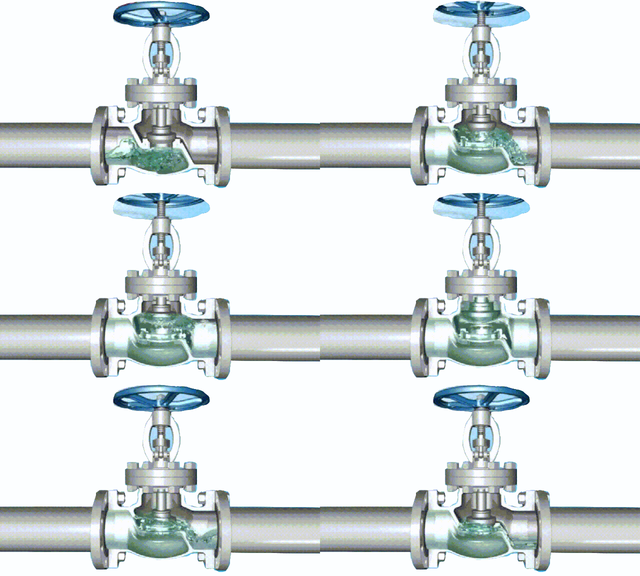
The closing principle of the electric shut-off valve is to rely on the electric thrust to rotate the valve stem, so that the sealing surface of the disc and the sealing surface of the valve seat are closely attached to prevent the medium from flowing. The electric shut-off valve only allows the medium to flow in one direction and is directional when installed. The structural length of the shut-off valve is longer than that of the gate valve, and the fluid resistance is large, and the sealing reliability is not strong during long-term operation.
1 In the closed position, the valve body is mechanically pressed by the valve stem, and the sealing surface of the valve clack is tightly pressed on the valve seat.
2 When turning the handwheel counterclockwise, the valve stem moves in the opposite direction, and the bottom angle plane makes the valve body separate from the valve seat.
3 The valve stem continues to lift, and interacts with the guide pin in the spiral groove of the valve stem, so that the valve flap starts to rotate without friction.
4 Until it reaches the fully open position, the valve stem is raised to the limit position and rotated to the fully open position.
Parameters of electric shut-off valve:
Valve material: cast iron, cast steel, stainless steel, forged steel, forged stainless steel, chromium molybdenum steel, low temperature steel.
Working pressure: 1.6-32MPa
Working temperature: -196°C-550°C
Valve diameter: DN15-DN800 Connection method: flange, wire or welding
Drive mode: electric
Applicable medium: water, oil, gas, steam, etc.
Application areas: mechanical equipment, chemical equipment, general parts, industrial equipment, water supply and drainage equipment, papermaking equipment, pharmaceutical equipment, general equipment, petrochemical equipment, power equipment, metallurgical powder equipment, mining equipment, municipal, electronic industry, etc.

TH Valve is a professional manufacturer of butterfly valvegate valvecheck valveglobe valveknife gate valve, ball valve with API, JIS, DIN standard, used in Oil, Gas, Marine industry, Water supply and drainage, fire fighting, shipbuilding, water treatment and other systems, with Nominal Diameter of DN50 to DN1200, NBR/EPDM/VITON, Certificates & Approvals: DNV-GL, Lloyds, DNV, BV, API, ABS, CCS. Standards: EN 593, API609, API6D

related news /knowledge: The working principle and characteristics of the globe valve; The difference and selection of electric valve and pneumatic valve; 

Installation and maintenance of electric ball valve

Installation and maintenance of electric ball valve
Electric ball valve is a kind of valve used to control the pipeline medium and can realize remote control. It is an important equipment in the current industrial automation control system. Including pneumatic ball valves, and other valves cannot be used continuously. After storage or use for a certain period of time, if you want to continue to ensure its effective work and appropriately extend its service life, maintenance and maintenance must be done.
Electric ball valve installation and maintenance:

electric ball valve

electric ball valve

1. When the electric ball valve is closed, there is still pressurized fluid inside the valve body;
2. Before maintenance, release the pipeline pressure and keep the valve in the open position; disconnect the power or air source; separate the actuator from the bracket;
3. It is necessary to find out that the upstream and downstream pipelines of the electric ball valve have indeed been relieved of pressure before the disassembly and decomposition operations can be carried out;
4. Care must be taken to prevent damage to the sealing surface of parts, especially non-metal parts, when disassembling and reassembling. Special tools should be used when removing O-rings;
5. The bolts on the flange must be tightened symmetrically, gradually and evenly during assembly;
6. The cleaning agent should be compatible with the rubber parts, plastic parts, metal parts and working medium (such as gas) in the ball valve. When the working medium is gas, gasoline (GB484-89) can be used to clean the metal parts. Clean non-metal parts with pure water or alcohol;
7. The decomposed individual parts can be cleaned by dipping. Metal parts with undecomposed non-metal parts can be scrubbed with a clean, fine silk cloth impregnated with cleaning agent (to prevent fibers from falling off and adhering to the parts). When cleaning, remove all grease, dirt, glue, dust, etc. adhering to the wall;
8. After cleaning, the non-metal parts should be taken out of the cleaning agent immediately, and should not be soaked for a long time;
9. After cleaning, it needs to be assembled after the cleaning agent of the washed wall surface is volatilized (can be wiped with a silk cloth not soaked in cleaning agent), but it should not be left for a long time, otherwise it will rust and be contaminated by dust;
10. New parts also need to be cleaned before assembling;
11. Use grease to lubricate. Grease should be compatible with ball valve metal materials, rubber parts, plastic parts and working medium. When the working medium is gas, for example, special 221 grease can be used. Apply a thin layer of grease on the surface of the seal installation groove, apply a thin layer of grease on the rubber seal, and apply a thin layer of grease on the sealing surface and friction surface of the valve stem;
12. Metal chips, fibers, grease (except those specified for use), dust, other impurities, foreign objects, etc., should not be allowed to contaminate, adhere or stay on the surface of the parts or enter the cavity during assembly.

Related knowledge: Pneumatic ball valve installation instructions

TH Valve is a professional manufacturer of butterfly valvegate valvecheck valveglobe valveknife gate valve, ball valve with API, JIS, DIN standard, used in Oil, Gas, Marine industry, Water supply and drainage, fire fighting, shipbuilding, water treatment and other systems, with Nominal Diameter of DN50 to DN1200, NBR/EPDM/VITON, Certificates & Approvals: DNV-GL, Lloyds, DNV, BV, API, ABS, CCS. Standards: EN 593, API609, API6D