Problems Existing in the Use of Triple Eccentric Butterfly Valves
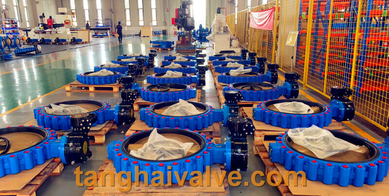
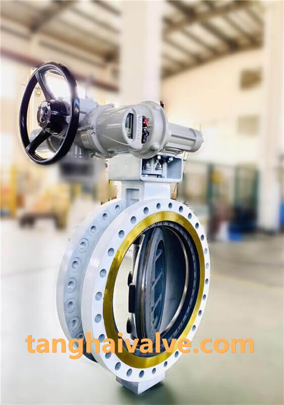
The triple eccentric metal seated butterfly valve is a high-quality valve category with high reliability and a wide range of applications. The triple eccentric butterfly valve is composed of main components such as valve body, butterfly
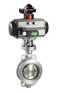
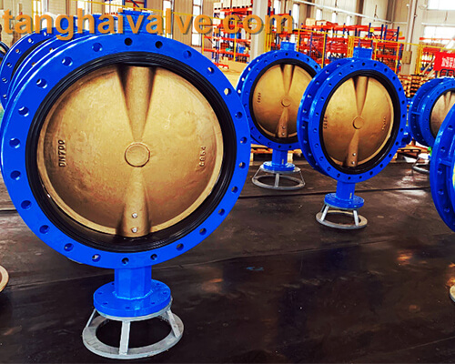
D673H-16C-stainless steel pneumatic triple eccentric butterfly valve
plate, valve stem, multi-layer metal sealing ring, shaft seal and drive mechanism. Its advantages are solid structure, good sealing performance, small torque, easy automatic control, etc. The triple eccentric butterfly valve is suitable for a variety of demanding working conditions, and has a wide range of applications in petroleum refining, natural gas extraction, chemical industry, power stations, metallurgy, and urban heating. However, things have two sides, and there are many problems in the use of the three-eccentric metal seated butterfly valve.
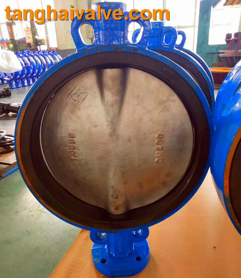
1. The butterfly plate of the triple eccentric butterfly valve is fixed with multiple layers of soft and hard stacked sealing rings. When the butterfly plate is in the open state, the circulating medium will directly wash the sealing surface. The soft sealing material in the metal sheet sandwich is in the long-term wash of the medium. It will directly affect the sealing performance of the valve.
2. The triple eccentric butterfly valve is not suitable for valves with a diameter smaller than DN200 because of its own structural constraints, the entire butterfly plate is very heavy and the flow resistance is very large.
3. The sealing between the butterfly plate sealing surface and the valve seat of the triple eccentric butterfly valve is to press the butterfly plate against the valve seat by the torque of the transmission device. When the medium in the pipeline is in a state of positive flow, the higher the pressure of the medium, the tighter the sealing and squeezing. But when the medium in the pipeline flows back, the pressure of the medium may cause seal leakage.
In order to solve the problems existing in the use of the triple eccentric butterfly valve, a high-performance triple eccentric two-way metal seated butterfly valve was developed. For the two-way sealing triple eccentric butterfly valve, the seat sealing ring is composed of multiple layers of stainless steel sheets on both sides of the soft T-shaped sealing ring. The sealing surface of the butterfly plate and the valve seat is an oblique cone structure, and then a high temperature and corrosion resistant alloy material is surfacing on the sealing surface of the oblique cone structure, and the spring fixed between the pressure plate of the adjusting ring and the adjusting bolt of the pressure plate are assembled together .
This special structure effectively compensates for the elastic deformation between the shaft sleeve of the triple eccentric butterfly valve and the valve body, and perfectly solves the problem that the triple eccentric butterfly valve is prone to leakage during the two-way interchangeable medium delivery process. The soft T-shaped sealing ring composed of multilayer stainless steel sheets on both sides not only has the advantages of a metal seated material, but also has the characteristics of a soft sealing material. Therefore, the three-eccentric butterfly valve with two-way sealing is suitable for both low temperature and high temperature conditions. Under the conditions, it can maintain excellent sealing performance.
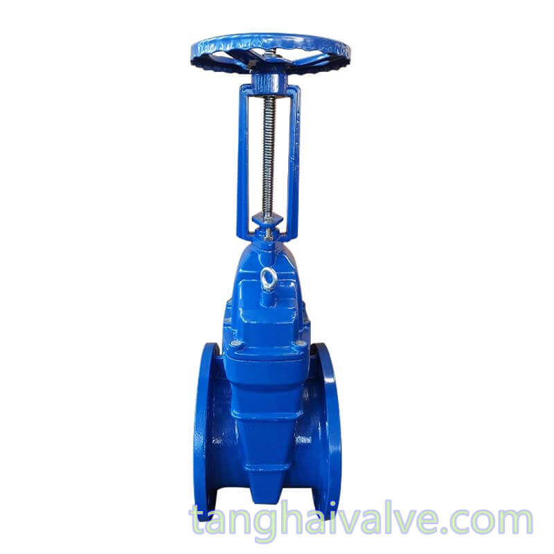
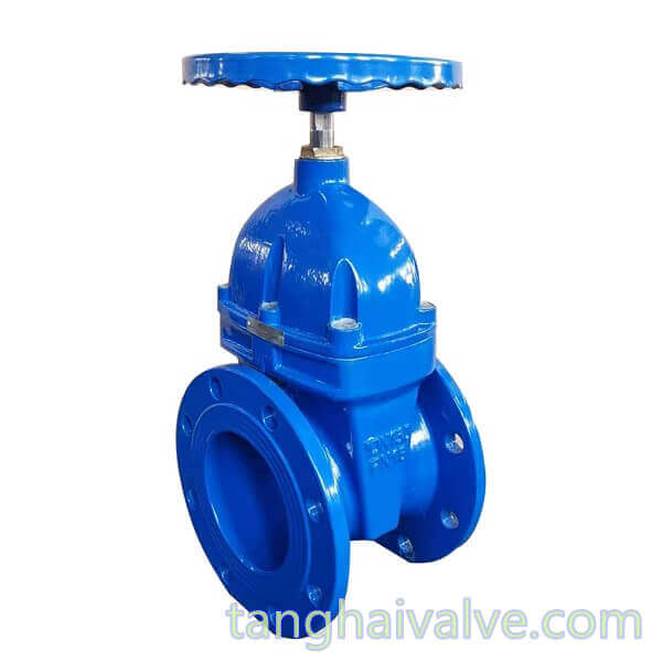
TH Valve is a professional manufacturer of butterfly valve, gate valve, check valve, globe valve, knife gate valve, ball valve with API, JIS, DIN standard, used in Oil, Gas, Marine industry, Water supply and drainage, fire fighting, shipbuilding, water treatment and other systems, with Nominal Diameter of DN50 to DN1200, NBR/EPDM/VITON, Certificates & Approvals: DNV-GL, Lloyds, DNV, BV, API, ABS, CCS. Standards: EN 593, API609, API6D
Related news/knowledge:
Selection and application of eccentric butterfly valve
The sealing characteristics and principle of eccentric butterfly valve
Electric ball valve-metal seated vs soft-seated type