The working principle of butterfly valve (picture)
Working principle of butterfly valve:
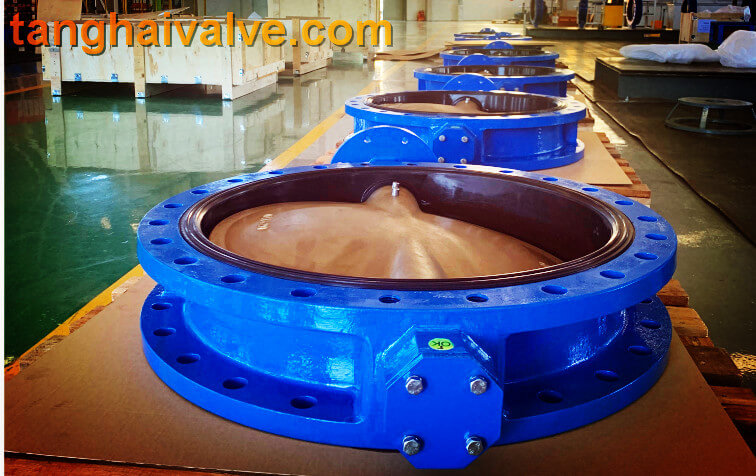
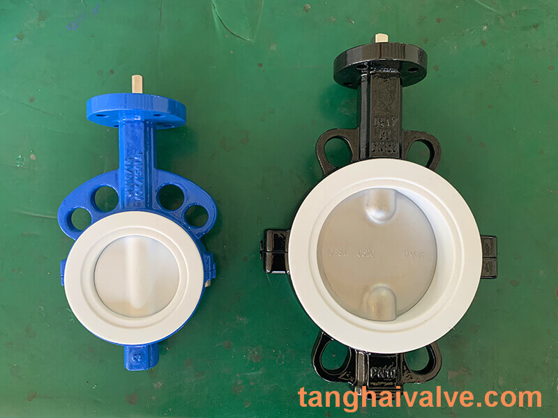
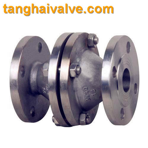
The butterfly valve is a valve that opens and closes according to the rotation of the valve stem, while driving the disc plate to rotate. In the cylindrical channel of the butterfly valve body, the disc-shaped butterfly plate rotates around the axis, mainly by rotating the disc plate 90° for flow control. When the disc reaches 90°, the valve is in a fully open state, and the angle of the disc can be changed to adjust the medium flow. It is generally installed in the
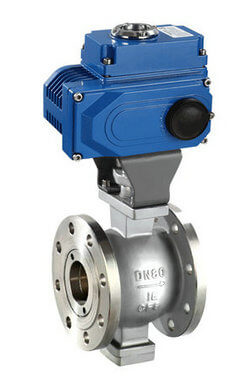
U-type-flange-butterfly-valve-2
diameter direction of the pipe. The butterfly valve and the valve stem have no locking ability. In order to effectively adjust the flow, a worm gear reducer is required. The butterfly valve with a worm gear reducer not only makes the butterfly valve self-locking, but also changes the operating performance of the butterfly valve and adjusts the medium flow more accurately. .
Features of butterfly valve:
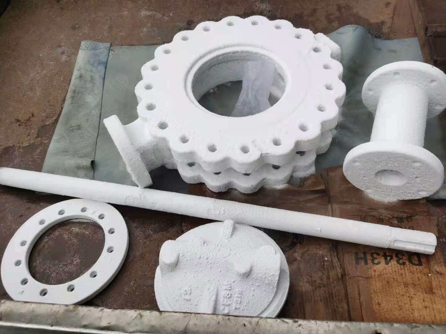
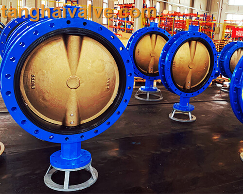
(1) Simple structure and small size. Due to its compact structure, short structure length, small size and light weight, it is suitable for large diameters.
(2) The fluid resistance is small. When fully opened, the effective flow area of the valve seat channel is large, so the fluid resistance is small.
(3) The opening and closing is convenient and rapid, the adjustment performance is good, and the butterfly plate rotates 90. Both can complete the opening and closing. The flow can be controlled in stages by changing the rotation angle of the butterfly plate.
(4) The opening and closing moment is small, because the discs on both sides of the rotating shaft are basically the same under the action of the medium, and the direction of the torque is opposite, so the opening and closing is labor-saving.
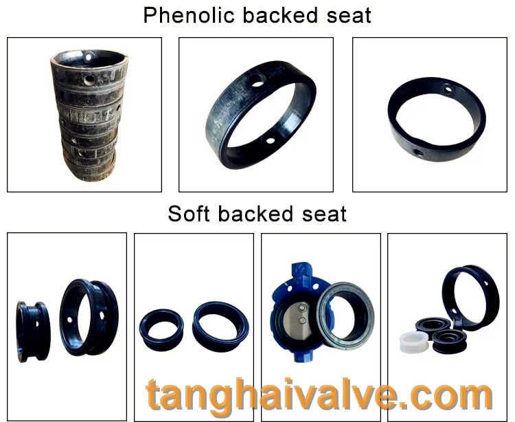
(5) The low-pressure sealing performance is good, and the sealing surface material is generally rubber or plastic, so the sealing performance is good. Limited by the material of the sealing ring, the operating pressure and operating temperature range of the butterfly valve is relatively small. However, the working pressure and working temperature range of the hard seal butterfly valve have been greatly improved.
butterfly valve working diagram-3D GIF animated presentation
1. The butterfly valve has a small flow resistance when it is fully opened. When the opening is between about 15° and 70°, it can carry out sensitive flow control. Therefore, the application of butterfly valves is very common in the field of large-diameter adjustment. Since the movement of the butterfly plate of the butterfly valve is wiping, most butterfly valves can be used for media with suspended solid particles. Depending on the strength of the seal, it can also be used for powder and granular media.
2. The butterfly valve is suitable for flow adjustment. Because the pressure loss of the butterfly valve in the pipe is relatively large, about three times that of the gate valve, when selecting the butterfly valve, the influence of the pressure loss of the piping system should be fully considered, and the strength of the butterfly plate to withstand the pressure of the pipeline medium when it is closed should also be considered. . In addition, it is necessary to consider the limitation of the working temperature that the elastic valve seat material can withstand at high temperatures. To
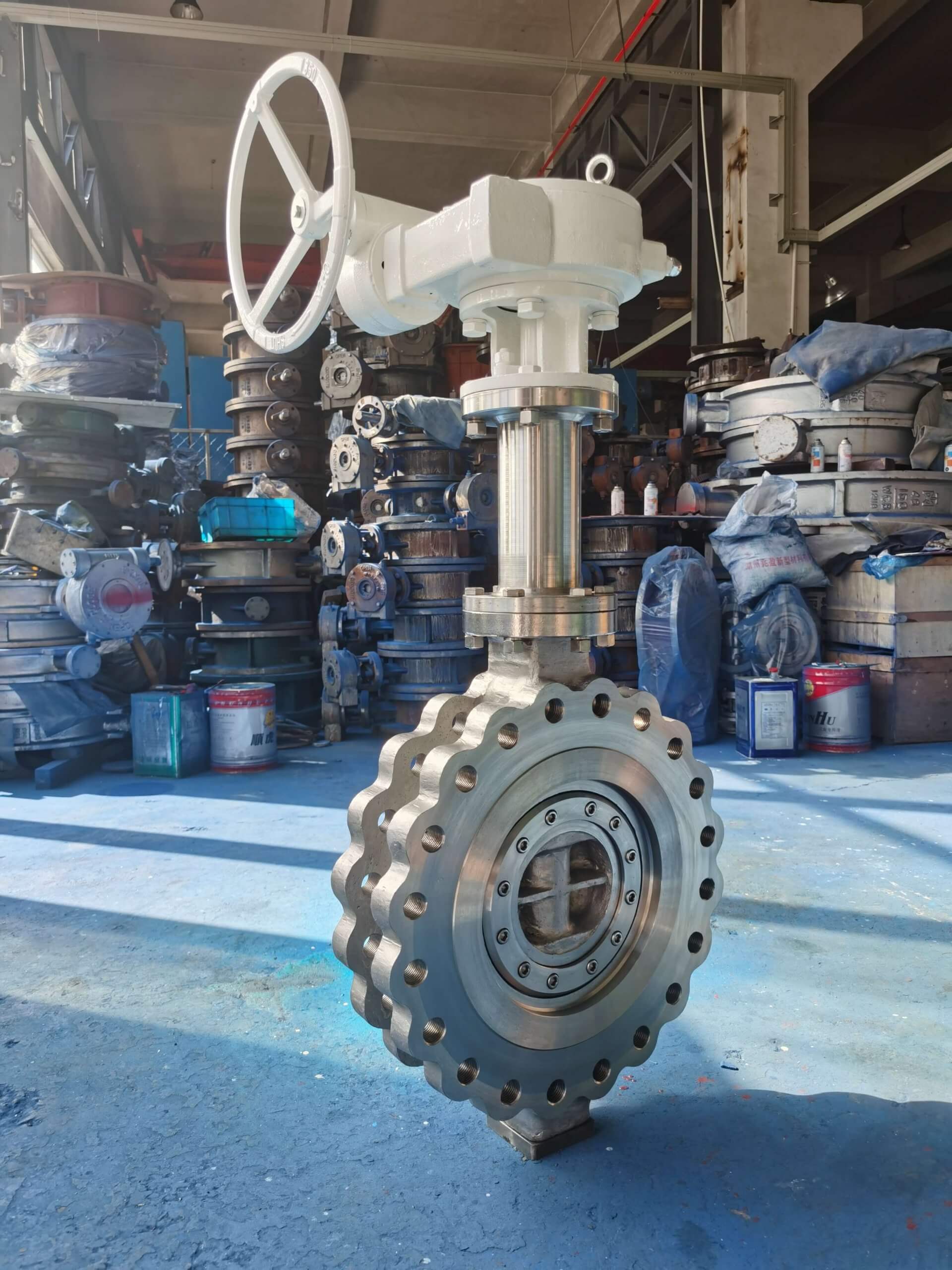
3. The structural length and overall height of the butterfly valve are small, the opening and closing speed is faster, and it has good fluid control characteristics. The structure principle of butterfly valve is most suitable for making large-diameter valves. When a butterfly valve is required to control flow, the most important thing is to correctly select the specification and type of the butterfly valve so that it can work properly and effectively.
Related knowledge: Principles of butterfly valve structure
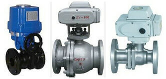
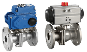
Related products: Electric switching butterfly valve Electric regulating butterfly valve
TH Valve is a professional manufacturer of butterfly valve, gate valve, check valve, globe valve, knife gate valve, ball valve with API, JIS, DIN standard, used in Oil, Gas, Marine industry, Water supply and drainage, fire fighting, shipbuilding, water treatment and other systems, with Nominal Diameter of DN50 to DN1200, NBR/EPDM/VITON, Certificates & Approvals: DNV-GL, Lloyds, DNV, BV, API, ABS, CCS. Standards: EN 593, API609, API6D