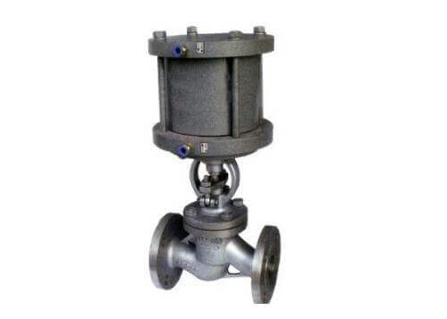
Working principle of pneumatic V-type regulating ball valve
The ball core of the pneumatic V-shaped regulating ball valve is designed with a special V-shaped notch, which has a shearing effect on the valve seat. It is especially suitable for media containing fibers, small solid particles, slurry and other media. According to different structural methods, it can generally be divided into flange and Wafer type; Pneumatic V-type ball valve is a fixed ball valve and also a single-seat sealed ball valve. It has the best adjustment performance among ball valves and can achieve flow adjustment. At the same time, since the valve core and seat are rotated without gaps, they can be wiped by themselves. The fouling on the ball and valve seat keeps a good seal between the ball and the valve seat.
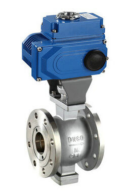
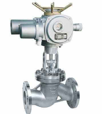
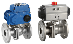
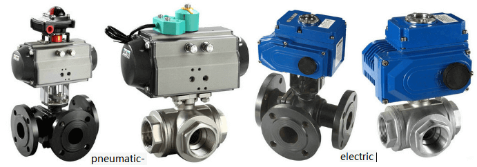
electric V type ball valve
Working principle of pneumatic V-shaped regulating ball valve:
Pneumatic V-shaped regulating ball valve realizes different degrees of proportionality according to the V-shaped angle of the V-shaped sphere. It is generally used in conjunction with a valve positioner to achieve proportional adjustment. The V-shaped spool is most suitable for various adjustment occasions and has a large rated flow coefficient. ,, The pressure loss is small, the use flow capacity is large, and it has accurate shut-off characteristics and control functions. The flow characteristics are approximately equal percentages. The opening and closing parts adopt the V-shaped ball structure, which completely solves the problem of easy deposition of medium in the valve cavity.
Features of pneumatic V-shaped regulating ball valve:
1. Pneumatic V-shaped ball valve V-shaped gap and valve seat produce a strong shear force to cut off impurities such as fibers, and has a self-cleaning function to avoid valve jamming.
2. The pneumatic V-type regulating ball valve has an inherent flow characteristic of approximately equal percentage and an adjustable ratio of up to 300:1, so it can provide precise control in a wide range of changes.
Note: Because the pneumatic V-type regulating ball valve is generally a single-seat sealed ball valve, it is not suitable for two-way use. Due to its streamlined shape and full right-angle rotation control, the maximum volume is extremely high, the flow capacity is particularly large, and the flow resistance is small.
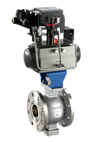
pneumatic V type ball valve
Pneumatic V-type regulating ball valve principle dynamic diagram
The valve core of the pneumatic V-shaped regulating ball valve is designed as a V-shaped gap with a special switch. The V-shaped gap and the valve seat generate a strong shear force, which can cut off high-viscosity media containing fibers or small solid particles, and has a self-cleaning function , To avoid the phenomenon of valve jamming. Pneumatic V-shaped ball valve is suitable for regulation and control, with high stability. Even in the case of small flow or high-viscosity medium, it can also ensure the accuracy of control within the entire range; while O-shaped ball valve is suitable for cutting off, relatively It is economical.
There is a V-shaped opening on the sphere of the pneumatic V-shaped regulating ball valve. As the ball rotates, the opening area changes, but the shape of the opening surface is always triangular. The flow characteristics are approximately equal percentages, the adjustable ratio is large, and the pressure loss is small. The flow capacity is large, and it has accurate interception characteristics and control functions. The opening and closing parts adopt a V-shaped spherical structure, which completely solves the problem of easy deposition of medium in the valve cavity. It is suitable for fibrous and slurry fluids!
The angle of the V-shaped port of the pneumatic V-shaped ball valve can be customized to meet more precise shut-off characteristics and control functions. Generally, more V-shaped valves are used in slurry media. They are similar to cam flex valves and are much better than O-shaped valves. V-shaped ball valves are used as regulating valves. For example, if the medium is not clean, the flow coefficient is low, and the leakage level is high, etc. occasion.
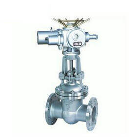
Working principle of electric V-type regulating ball valve
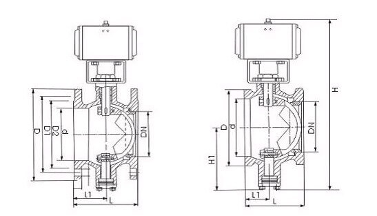
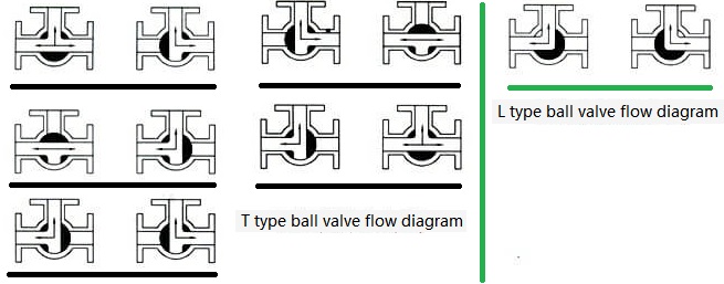
V type ball valve drawing
The electric V-shaped regulating ball valve has a special-shaped V-shaped incision. When the valve is closed, the V-shaped incision and the valve seat form a wedge shape, which has a shearing effect. The electric V-shaped ball valve is suitable for the control of fibrous slurry, sewage and viscous particle media. It can prevent the seizure of dirt between the ball and the valve seat. It has a self-cleaning function and is a wide-ranging regulating valve.
When the electric V-shaped ball valve rotates, the V-shaped blade of the ball is tangent to the valve seat, thereby cutting off the fiber and solid matter in the fluid. However, the general ball valve does not have this function, so it is easy to cause the fiber impurities to get stuck when closed. , Bring great inconvenience to repair and maintenance. The valve core of the electric V-shaped ball valve will not be jammed by the fiber, and the flow rate of the pipeline medium is adjusted and controlled according to the change of the opening area of the V-shaped gap.
Note: Since the electric V-type regulating ball valve is generally a single-seat sealing ball valve, it is not suitable for two-way use. The integral valve body structure is adopted, and there is no potential for leakage.
Features of electric V-shaped ball valve:
1. It has the advantages of compact structure, small volume, vertical and horizontal installation, etc., adopts movable metal valve seat, self-compensation function, and has superior sealing performance and long service life.
2. The electric V-shaped ball valve adopts a double-bearing structure, which has high mechanical stability and low starting torque, which ensures that the valve has excellent sensitivity and induction speed.
3. Maximum reliability (safety): The valve body is a whole, sturdy and durable, operation is not affected by pipeline pressure, and leakage of the valve body can be avoided.
4. The V-shaped gap and valve seat of the electric V-shaped regulating ball valve produce a strong shearing force to cut off impurities such as fibers, and has a self-cleaning function to avoid valve jamming.
5. Maximum flow volume: Due to the streamlined shape of the electric V-shaped ball valve and the full right-angle rotation control, the maximum volume is particularly high, the flow capacity is particularly large, and the flow resistance is small.
TH Valve is a professional manufacturer of butterfly valve, gate valve, check valve, globe valve, knife gate valve, ball valve with API, JIS, DIN standard, used in Oil, Gas, Marine industry, Water supply and drainage, fire fighting, shipbuilding, water treatment and other systems, with Nominal Diameter of DN50 to DN1200, NBR/EPDM/VITON, Certificates & Approvals: DNV-GL, Lloyds, DNV, BV, API, ABS, CCS. Standards: EN 593, API609, API6D
related news /knowledge:
O type |V type ball valve structure principle;
The role and classification of valves;
Pneumatic ball valve-with high platform vs with bracket;
The working principle of the ball valve (GIF)