Types of mechanical transmission
There are many forms of mechanical transmission, which can be divided mainly into two categories:
1. Friction transmission that transmits power and motion by friction between parts, including belt transmission, rope transmission and friction wheel transmission. Friction transmission is easy to achieve stepless speed change, and it can mostly adapt to transmission occasions with large shaft spacing. Overload and slip can also play a role in buffering and protecting the transmission device. However, this type of transmission is generally not used in high-power applications and cannot guarantee accuracy. The transmission ratio.
2. The meshing transmission of power or movement by the meshing of the driving part and the driven part or the meshing of intermediate parts, including gear transmission, chain transmission, spiral transmission and harmonic transmission. The meshing transmission can be used in high-power applications with accurate transmission ratio, but generally requires higher manufacturing accuracy and installation accuracy.
According to the forms of force transmission, mechanical transmission can be divided into:
1 Friction drive.
2 Chain drive.
3 Gear drive.
4 Belt drive.
5 Turbo worm drive.
6 Ratchet drive.
7 Crankshaft connecting rod drive
8 Pneumatic transmission.
9 Hydraulic drive (hydraulic planer)
10 Universal joint drive
11 Wire rope drive (most widely used in elevators)
12 coupling drive
13 Spline transmission.
1. Features of belt drive
Including driving wheel, driven wheel and endless belt.
1) It is used in the situation where the two axes are parallel and the rotation direction is the same, which is called the concept of opening motion, center distance and wrap angle.
2) The belt type can be divided into three categories: flat belt, V belt and special belt according to the cross-sectional shape.
3) The focus of application is: calculation of transmission ratio, stress analysis and calculation of belt, and allowable power of a single V belt.
Advantages-suitable for transmission with a large center distance between two axles; the belt has good flexibility, can alleviate impact and absorb vibration; slip when overloaded to prevent damage to other parts; simple structure and low cost.
Because the belt is elastic and is driven by friction, it has a simple structure, stable transmission, low noise, and can buffer and absorb vibration. When overloaded, the belt will slip on the pulley and protect other parts from overload. It is suitable for center distance Advantages such as larger transmission.
But belt transmission also has many shortcomings. The main ones are: accurate transmission ratio cannot be guaranteed, transmission efficiency is low (approximately 0.90~0.94), belt service life is short, and it is not suitable for use in high temperature, flammable, oil and water situations.
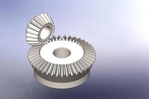
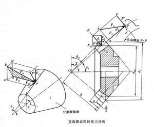
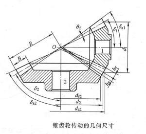
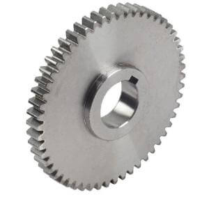
2. Gear transmission
Classification: plane gear transmission, space gear transmission.
Features
Advantages-Wide range of applicable peripheral speed and power; accurate, stable, and high-efficiency transmission ratio; high reliability and long life; transmission between parallel shafts, intersecting shafts at any angle and intersecting shafts at any angle can be realized.
Disadvantages-requires higher manufacturing and installation accuracy, higher cost; not suitable for long-distance transmission between two shafts.
The names of the basic dimensions of involute standard gears include addendum circle, tooth root circle, index circle, touch number, pressure angle, etc.
1. The range of power and speed transmitted by the gear is very large, the power can be as small as hundreds of thousands of kilowatts, and the peripheral speed can be as small as more than one hundred meters per second. The gear size can range from less than 1mm to more than 10m.
2. Gear transmission belongs to meshing transmission, the gear tooth profile is a specific curve, the instantaneous transmission ratio is constant, and the transmission is stable and reliable.
3. High gear transmission efficiency and long service life.
4. There are many kinds of gears, which can meet the needs of various transmission forms.
5. The manufacturing and installation of gears require high precision.
4. Features of chain drive
1) To ensure a more accurate transmission ratio (compared with belt transmission)
2) Power can be transmitted when the center distance between the two shafts is far (compared to gear transmission)
3) Can only be used for transmission between parallel shafts
4) After the chain wears out, the chain links become longer, which is easy to cause chain disconnection.
5. Worm gear drive
It is suitable for movement and dynamics between two axes that are vertical and not intersecting in space.
Features
Advantages-large transmission ratio. ; Compact structure size.
Disadvantages-large axial force, easy to heat, low efficiency; only one-way transmission.
The main parameters of the worm gear drive are: modulus, pressure angle, worm gear index circle, worm index circle, lead, number of worm gear teeth, number of worm heads, transmission ratio, etc.
Single-stage transmission can obtain a large transmission ratio, compact structure, smooth transmission, no noise, but low transmission efficiency. Two-stage transmission solves the shortcomings of single-stage transmission.
6. The characteristics of spiral transmission: high transmission accuracy, stable operation, no noise, easy to self-lock, and can transmit greater power.
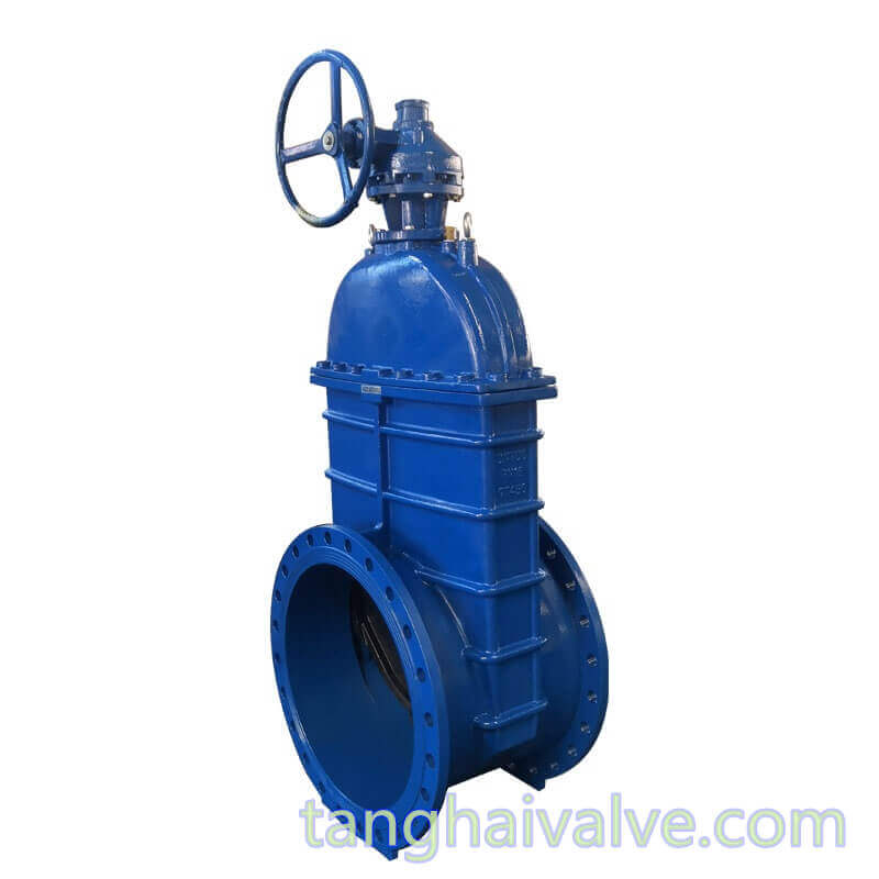
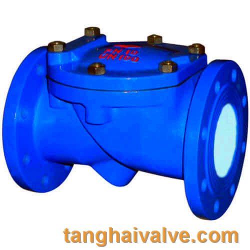
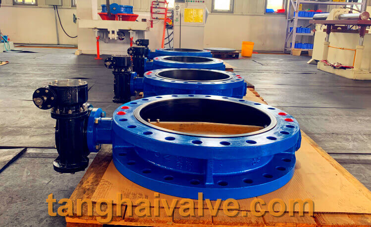
In the valve industry, there are many ways to open and close the valve plate. we call it valve drive method. as below:
Unit two, valve drive mode (code name):
| drive mode | Electro-magne-tism | Electro-magnetic hydraulic | Electro-hydraulic | tur-bine | Spur gear | Bevel gear | pneu-matic | Hydr-aulic | Gas-hydr-aulic | elec-tric | han-dle | Hand-wheel |
| code | 0 | 1 | 2 | 3 | 4 | 5 | 6 | 7 | 8 | 9 |
See the link for more details: https://www.tanghaivalve.com/valve-model-establishment-and-meaning/
TH Valve is a professional manufacturer of butterfly valve, gate valve, check valve, globe valve, knife gate valve, ball valve with API, JIS, DIN standard, used in Oil, Gas, Marine industry, Water supply and drainage, fire fighting, shipbuilding, water treatment and other systems, with Nominal Diameter of DN50 to DN1200, NBR/EPDM/VITON, Certificates & Approvals: DNV-GL, Lloyds, DNV, BV, API, ABS, CCS. Standards: EN 593, API609, API6D
Related news/knowledge:
What is the transmission ratio
What is the positive transmission of gears
Form and types of Gear transmission
Stainless steel valve material parameters and specific applications