What is butt welding? (4)- flash butt welding

2. Resistance and heating of flash butt welding

The contact resistance Rc during flash butt welding is the total resistance of the liquid metal lintel between the end faces of the two workpieces, and its size depends on the number of lintels and their cross-sectional area at the same time. The latter two are related to the cross-sectional area of ​​the workpiece, the current density and the

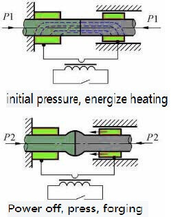
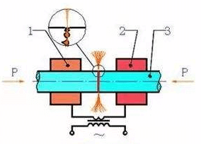
flash butt welding-schematic diagram

flash butt welding-schematic diagram

approach speed of the two workpieces. With the increase of these three, the number of lintels and their cross-sectional area simultaneously existing increases, and Rc will decrease.

The Rc of flash butt welding is much larger than that of resistance butt welding, and it exists throughout the flashing stage. Although its resistance value gradually decreases, it is always greater than the internal resistance of the workpiece. Rc does not disappear completely until the upsetting starts. Figure 14-5 shows the general law of Rc, 2Rω and R changes during flash butt welding. The gradual decrease in Rc is due to the increase in the approach speed of the workpiece as the end surface temperature increases during the flashing process, and the number and size of the lintels increase accordingly.

Because Rc is large and there is the entire flashing stage, the heating of the joint during flash butt welding mainly depends on Rc.

Three, flash butt welding welding cycle, process parameters and workpiece preparation

1, welding cycle

The welding cycle of flash butt welding is shown in 14-7, and the reset time in the figure refers to the time from loosening the workpiece to returning to the original position. There are two preheating methods: resistance preheating and flashing preheating. The figure (b) uses resistance preheating.

2, process parameters

The main parameters of flash butt welding are: extension length, flash current, flash flow, flash speed, upsetting flow, upsetting speed, upsetting pressure, upsetting current, clamping force, etc. Figure 14-8 is a schematic diagram of each flow rate and extension length of continuous flash butt welding. The following describes the influence of various process parameters on welding quality and the principles of selection:

(1) Elongation length l0 is the same as resistance butt welding, l0 affects the temperature distribution along the axial direction of the workpiece and the plastic deformation of the joint. In addition, with the increase of l0, the impedance of the welding circuit increases, and the required power also increases. Under normal circumstances, bar and thick arm tube l0=(0.7-1.0)d, d is the diameter of the round bar or the side length of the square bar.

For thin plates (δ=1-4mm), in order not to lose stability during upsetting, generally l0=(4-5)δ.

When different metals are butt welded, in order to make the temperature distribution on the two workpieces consistent, usually the metal with poor electrical and thermal conductivity should be smaller. Table 1 is the l0 reference value for flash butt welding of different metals.

(2) The flash current If and the upsetting current Iu If depend on the cross-sectional area of ​​the workpiece and the current density jf required for the flash. The size of jf is related to the physical properties of the welded metal, flashing speed, the area and shape of the workpiece section, and the heating state of the end surface. In the flashing process, as vf gradually increases and contact resistance Rc gradually decreases, jf will increase. During the upsetting, Rc disappears quickly, and the current will increase sharply to the upsetting current Iu. When welding large-section steel parts, in order to increase the heating depth of the workpiece, a smaller flash speed should be used, and the average jf used generally does not exceed 5A/mm2. Table 2 shows the reference values ​​of jf and ju for flash butt welding of workpieces with a cross-sectional area of ​​200-1000mm2.

The magnitude of the current depends on the no-load voltage U20 of the welding transformer. Therefore, in actual production, the secondary no-load voltage is generally given. When selecting U20, in addition to considering the impedance of the welder circuit, when the impedance is large, U20 should be increased accordingly. When welding large-section workpieces, the method of adjusting the secondary voltage in stages is sometimes used. At the beginning, a higher U20 is used to excite the flash, and then it is reduced to an adaptive value.

(3) Flash flow rate δf The flash flow rate should be selected so that there is a molten metal layer on the end of the workpiece at the end of the flash, and the plastic deformation temperature is reached at a certain depth. If δf is too small, the above requirements cannot be met, which will affect the welding quality. If δf is too large, it will waste metal materials and reduce productivity. When choosing δf, you should also consider whether there is preheating, because the δf of preheating flash butt welding can be 30-50% smaller than continuous flash butt welding.

What is butt welding? (3)- flash butt welding

Flash butt welding

Flash butt welding can be divided into continuous flash butt welding and preheated flash butt welding. Continuous flash butt welding consists of two main stages: the flash stage and the upsetting stage. Preheating flash butt welding only adds a preheating stage before the flashing stage.

flash butt welding-schematic diagram

flash butt welding-schematic diagram

One, two stages of flash butt welding

1, flash stage

The main function of flash is to heat the workpiece. In this stage, the power is turned on first, and the end faces of the two workpieces are slightly contacted, forming many contact points. When the current passes, the contact points melt and become liquid metal lintels connecting the two ends. Due to the extremely high current density in the liquid lintel, the liquid metal in the lintel evaporates and the lintel blasts. With the slow advancement of the movable clamp, the lintels are also continuously produced and blasted. Under the action of vapor pressure and electromagnetic force, liquid metal particles are continuously ejected from the interface. The formation of a rapid stream of sparks-flash.

In the flashing process, the workpiece gradually shortens and the temperature of the tip gradually rises. As the end temperature increases, the blasting speed of the lintel will increase, and the advancing speed of the movable clamp must be gradually increased. Before the flashing process ends, a layer of liquid metal must be formed on the entire end surface of the workpiece, and the metal must reach the plastic deformation temperature at a certain depth.

Due to the strong oxidation of metal vapor and metal particles generated during lintel blasting, the oxygen content of the gas medium in the interface gap is reduced, and its oxidation capacity can be reduced, thereby improving the quality of the joint. But the flash must be stable and strong. The so-called stability means that no open circuit or short circuit occurs during the flashing process. The open circuit will weaken the self-protection effect of the weld, and the joint will be easily oxidized. A short circuit will overburn the workpiece and cause the workpiece to be scrapped. The so-called strong means that there are quite a lot of lintel blasts per unit time. The stronger the flash, the better the self-protection of the weld, which is especially important in the later flash.

2, upsetting stage

At the end of the flashing stage, immediately apply sufficient top pressure to the workpiece, and the interface gap is rapidly reduced, and the lintel stops blasting, that is, the upsetting stage is entered. The function of upsetting is to seal the gap between the end face of the workpiece and the fire hole left by the liquid metal lintel after blasting, while extruding the liquid metal and oxide inclusions on the end face, so that the clean plastic metal is in close contact, and the joint area produces a certain degree of plasticity Deformation to promote the progress of recrystallization, form common crystal grains, and obtain a strong joint. Although there is molten metal during the heating process in flash butt welding, it is actually welding in a plastic state.

Preheating flash butt welding is to heat the workpiece with intermittent current pulses before the flash phase, and then enter the flash and upsetting phase. The purpose of preheating is as follows:

(1) Reduce the required power to weld workpieces with larger cross-sectional area on a small capacity welder, because when the capacity of the welder is insufficient, it is impossible to stimulate continuous flashing without preheating the workpiece to a certain temperature. process. At this time, preheating is a last resort.

(2) Reduce the cooling rate after welding. This will help prevent the quenched structure and cracks of the quenched steel joint during cooling.

(3) Shortening the flash time can reduce the flash margin and save precious metals.

The shortcomings of preheating are:

(1) Extend the welding cycle and reduce the productivity;

(2) Make the process automation more complicated;

(3) Preheating control is difficult. If the preheating degree is inconsistent, the stability of the joint quality will be reduced.

TH Valve is a professional manufacturer of butterfly valvegate valvecheck valveglobe valveknife gate valve, ball valve with API, JIS, DIN standard, used in Oil, Gas, Marine industry, Water supply and drainage, fire fighting, shipbuilding, water treatment and other systems, with Nominal Diameter of DN50 to DN1200, NBR/EPDM/VITON, Certificates & Approvals: DNV-GL, Lloyds, DNV, BV, API, ABS, CCS. Standards: EN 593, API609, API6D

Related news/knowledge:
What is butt welding? (5)- flash butt welding;
What is butt welding? (4)- flash butt welding;
What is butt welding? (7)- Flash butt welding of common metals;
What is butt welding? (1)

What is butt welding? (2)

2. Welding cycle, process parameters and workpiece preparation for resistance butt welding

1, welding cycle

During resistance butt welding, the two workpieces are always pressed tightly. When the end face temperature rises to the welding temperature Tω, the distance between the end faces of the two workpieces is as small as a few

resistance butt welding-Schematic diagram

resistance butt welding-Schematic diagram

angstroms. The atoms between the end faces interact to produce common crystal grains on the joint. Form joints. There are two welding cycles in resistance butt welding: equal pressure and increased forging pressure. The former is simple and easy to implement. The latter is conducive to improving the quality of welding, and is mainly used for

resistance butt welding of alloy steel, non-ferrous metals and their alloys. In order to obtain sufficient plastic deformation and further improve the quality of the joint, a current upsetting procedure should be set.

2, process parameters

The main process parameters of resistance butt welding are: extension length, welding current (or welding current density), welding energization time, welding pressure and upsetting pressure.

(1) Overhang length l0 is the length of the workpiece over the end face of the clamp electrode. When selecting the extension length, two factors should be considered: the stability of the workpiece during upsetting and the heat dissipation to the clamp. If l0 is too long, the workpiece will lose stability during upsetting. If l0 is too short, due to the enhanced heat dissipation to the jaws, the workpiece will be cooled too strongly, which will increase the difficulty of plastic deformation. For the workpiece with diameter d, generally low carbon steel: l0=(0.5-1)d, aluminum and brass: l0=(1-2)d, copper: l0=(1.5-2.5)d.

(2) Welding current Iω and welding time tω In resistance butt welding, the welding current is often expressed by the current density jω. jω and tω are the two main parameters that determine the heating of the workpiece. The two can be adjusted accordingly within a certain range. High current density and short time (strong condition) can be used, or low current density and long time (weak condition) can be used. But when the condition is too strong, it is easy to produce incomplete penetration defects; when it is too soft, it will cause serious oxidation of the interface end surface, coarse grains in the joint area, and affect the strength of the joint.

(3) The welding pressure Fω and the upsetting pressure Fu, Fω have an effect on the heat generation and plastic deformation of the joint. Reducing Fω is good for heat generation, but not good for plastic deformation. Therefore, it is easy to use a smaller Fω for heating and a much larger Fu for upsetting. However, Fω should not be too low, otherwise it will cause splashing, increase end surface oxidation, and cause looseness near the interface.

3. Workpiece preparation

In resistance butt welding, the shape and size of the end faces of the two workpieces should be the same to ensure that the heating and plastic deformation of the workpieces are consistent. The end surface of the workpiece and the surface in contact with the clamp must be strictly cleaned. Oxide and dirt on the end face will directly affect the quality of the joint. The oxides and dirt on the surface of the workpiece in contact with the clamp will increase the resistance of the contact, which will cause the surface of the workpiece to burn, increase the wear of the jaws, and increase the power loss.

The workpiece can be cleaned by mechanical means such as grinding wheels, wire brushes, etc., or pickling.

Oxide inclusions easily occur in resistance welding joints. For rare metals, certain alloy steels and non-ferrous metals with high welding quality requirements, protective atmospheres such as argon and helium are often used to solve the problem.

Although resistance butt welding has the advantages of smooth joints, small burrs, and simple welding process, the mechanical properties of the joints are low, and the preparation of the end face of the workpiece is high, so it is only used for butt joints of small section (less than 250mm2) metal profiles.

What is butt welding? (1)

Butt resistance welding (hereinafter referred to as butt welding) is a type of resistance welding method that uses resistance heat to weld two workpieces along the entire end surface at the same time. Butt welding has high

welding

welding

productivity and easy automation, so it is widely used.
Application of butt welding:
Butt welding has high productivity and easy automation, so it is widely used. Its application range can be summarized as follows:
(1) The length of the work piece, such as the butt welding of strip steel, profile, wire, steel bar, rail, boiler steel pipe, oil and natural gas transportation pipeline.
(2) Butt welding of annular workpieces, such as car rims and bicycles, motorcycle rims, butt welding of various chain links, etc.
(3) Assembling welding of components The simple rolling, forging, stamping or machining parts are butt-welded into complex parts to reduce costs. For example, butt welding of automobile steering shaft shell and rear axle housing, butt welding of various connecting rods and tie rods, and butt welding of special parts.
(4) Butt welding of dissimilar metals can save precious metals and improve product performance. For example, the butt welding of the working part of the tool (high-speed steel) and the tail (medium carbon steel), the butt welding of the head (heat-resistant steel) and the tail (structural steel) of the exhaust valve of an internal combustion engine, the butt welding of aluminum and copper conductive joints, etc. .
Classification of butt welding:
Butt welding is divided into resistance butt welding and flash butt welding.
Resistance butt welding
Resistance butt welding is a method in which the end faces of the two workpieces are always pressed tightly, heated to a plastic state by resistance heat, and then upset pressure is quickly applied (or no upset pressure is applied and only the pressure during welding is maintained) to complete the welding.
One, resistance and heating of resistance butt welding
The resistance distribution during butt welding is shown in the figure. The total resistance can be expressed by the following formula:
R=2Rω+RC+2Reω
where Rω-the internal resistance of the conductive part of a workpiece (Ω);
Rc–the contact resistance between two workpieces (Ω);
Rω–The contact resistance between the workpiece and the electrode (Ω);
The contact resistance between the workpiece and the electrode is usually ignored due to its small resistance and far from the joint surface.
The internal resistance of the workpiece is proportional to the resistivity ρ of the welded metal and the length l0 of the workpiece extending from the electrode, and inversely proportional to the cross-sectional area s of the workpiece.
Same as spot welding, the contact resistance of resistance butt welding depends on the surface condition, temperature and pressure of the contact surface. When the contact resistance has obvious oxides or other stolen goods, the contact resistance is large. The increase in temperature or pressure will reduce the contact resistance due to the increase in the actual contact area. At the beginning of welding, the current density at the contact point is very large; after the end surface temperature rises rapidly, the contact resistance decreases sharply. When heated to a certain temperature (steel 600 degrees, aluminum alloy 350 degrees), the contact resistance disappears completely.
Like spot welding, the heat source during butt welding is also the resistance heat generated by the resistance of the welding zone. In resistance butt welding, the contact resistance exists for a very short time, and the heat generated is less than 10-15% of the total heat. But because this part of the heat is generated in a very narrow area near the contact surface. Therefore, the temperature in this area will increase rapidly, and the internal resistance will increase rapidly. Even if the contact resistance disappears completely, the heat generation intensity in this area is still higher than other places.
The harder the welding rod used (that is, the larger the current and the shorter the energization time), the smaller the pressing force of the workpiece, and the more obvious the influence of contact resistance on heating.

Classification and characteristics of welding

Metal welding can be divided into three categories: fusion welding, pressure welding and brazing according to the characteristics of the process. The characteristics are:
1. Fusion welding: heat the workpiece to be joined to partially melt it to form a molten pool. The molten pool will be joined after cooling and solidification. If necessary, a filler can be added to assist. It is suitable for welding of various

welding

welding

metals and alloys without pressure. .
2. Pressure welding: The welding process must apply pressure to the weldment, which belongs to the processing of various metal materials and some metal materials.
3. Brazing: Use metal materials with a lower melting point than the base material as the brazing filler metal, and use the liquid brazing filler metal to wet the base material, fill the joint gap, and mutually diffuse with the base metal to realize the connection of the weldment. Suitable for welding of various materials, and also suitable for welding of different metals or dissimilar materials.

Welding equipment can be divided into manual welding equipment and automatic welding equipment according to the degree of welding automation.
During the welding process, if the atmosphere is in direct contact with the high-temperature molten pool, the oxygen in the atmosphere will oxidize metals and various alloying elements. Nitrogen and water vapor in the atmosphere enter the molten pool, and will also form pores, slag inclusions, cracks and other defects in the weld during the subsequent cooling process, which will deteriorate the quality and performance of the weld.
There are many energy sources for modern welding, including gas flame, electric arc, laser, electron beam, friction and ultrasonic. In addition to being used in factories, welding can also be carried out in a variety of environments, such as the field, underwater and space.

No matter where it is, welding may bring danger to the operator, so appropriate protective measures must be taken when welding. The possible harm caused by welding to the human body includes burns, electric shocks, visual impairment, inhalation of toxic gases, and excessive ultraviolet radiation.
In order to improve the welding quality, various protection methods have been developed. For example, gas shielded arc welding is to isolate the atmosphere with argon, carbon dioxide and other gases to protect the arc and molten pool rate during welding.

For example, when welding steel, adding ferro-titanium powder with high oxygen affinity to the electrode coating for deoxidation can protect the beneficial elements such as manganese and silicon in the electrode from oxidation and enter the molten pool. After cooling, high-quality welds can be obtained.

The common feature of various pressure welding methods is to apply pressure during the welding process without adding filler materials. Most pressure welding methods, such as diffusion welding, high frequency welding, cold pressure welding, etc., do not have a melting process, so there is no problem like fusion welding, which has beneficial alloying elements burning and harmful elements intruding into the weld, thus simplifying the welding process. It also improves welding safety and health conditions.

At the same time, because the heating temperature is lower than that of fusion welding and the heating time is shorter, the heat affected zone is small. Many materials that are difficult to weld by fusion welding can often be welded by pressure welding to form a high-quality joint with the same strength as the base metal.

TH Valve is a professional manufacturer of butterfly valvegate valvecheck valveglobe valveknife gate valve, ball valve with API, JIS, DIN standard, used in Oil, Gas, Marine industry, Water supply and drainage, fire fighting, shipbuilding, water treatment and other systems, with Nominal Diameter of DN50 to DN1200, NBR/EPDM/VITON, Certificates & Approvals: DNV-GL, Lloyds, DNV, BV, API, ABS, CCS. Standards: EN 593, API609, API6D

Related news/knowledge:

What is butt welding? (7)- Flash butt welding of common metals;

What is butt welding? (6)- Flash butt welding of common metals;

What is butt welding? (1); What is butt welding? (2)

Valve model establishment and meaning

The latest valve model compilation method
Nowadays, there are more and more types of valves and materials, and the compilation of valve models is becoming

ductile iron, DI, butterfly valve, manufacturer, center line, TH valve

ductile iron, DI, butterfly valve, manufacturer, center line, TH valve

more and more complicated. The standardization of valve models provides convenience for valve design and selection. Although my country has a unified standard for valve model compilation, it is gradually unable to meet the needs of the development of the valve industry. At present, valve manufacturers generally adopt a unified numbering method; if a unified numbering method cannot be used, each manufacturer can work out a numbering method according to its own situation.
The valve model compilation method specifies the valve model description, valve type, drive mode, connection form, structure form, sealing surface material, pressure and the expression method of the valve body material code. The valve model preparation method is suitable for all kinds of pipeline valves such as gate valves, globe valves, throttle valves, butterfly valves, ball valves, diaphragm valves, plug valves, check valves, drain valves, plunger valves, pressure reducing valves, traps, and safety valves. product. Standard valve model representation method The valve model compilation method should usually indicate the valve type, drive mode, connection form, structural characteristics, nominal pressure, sealing surface material, valve body material and other elements.
Unit One , valve type (code name):

butterfly valve safety valve Diaph-ragm valve ball valve gate valve check valve plug valve Pressure reducing valve globe valve filter Disch-arge valve
D A G Q Z H X Y J GL FL

Unit two, valve drive mode (code name):

drive mode Electro-magne-tism Electro-magnetic hydraulic Electro-hydraulic tur-bine Spur gear Bevel gear pneu-matic Hydr-aulic Gas-hydr-aulic elec-tric han-dle Hand-wheel
code 0 1 2 3 4 5 6 7 8 9

Unit three, valve connection method (code name):

connection internal thread external thread two different connections flange welding wafer clamp ferrule
code 1 2 3 4 6 7 8 9

Unit Four, valve structure (code name):

Butterfly valve structure (code name):

butterfly structure butterfly code butterfly structure butterfly code
sealed singl eccentric 0 unsealed single eccentric 5
center vertical plate 1 center vertical plate 6
double eccentric 2 double eccentric 7
triple eccentric 3 triple eccentric 8
linkage mechanism 4 linkage mechanism 9

Gate valve structure (code name):

gate valve structure types gate valve code
valve stem lift type Wedge gate plate Flexible gate plate 0
rigid gate plate single gate 1
double gates 2
Parallel gate plate single gate 3
double gates 4
non-lifting valve stem Wedge gate plate single gate 5
double gates 6
Parallel gate plate single gate 7
double gates 8

Ball valve structure (code name):

ball valve structure code ball valve structure code
floating ball Straight flow channel 1 fixed ball Straight flow channel 7
Y type three-way channel 2 four-way channel 6
L type three-way channel 4 T type three-way channel 8
Y type three-way channel 5 L type three-way channel 9
Hemisphere through 0

Check valve structure (code name):

check valve structure code check valve structure code
lifting disc straight flow channel 1 swing disc single disc 4
vertical structure 2 multiple discs 5
angle channel 3 double disc 6
butterfly type check valve 7

The structure of stop valve, throttle valve and plunger valve (code name):

globe valve structure code globe valve structure code
disc type unbalanced straight flow channel 1 disc type balanced straight flow channel 6
Z channel 2 angle channel 7
three-way channel 3
angle channel 4
DC runner 5

Diaphragm valve structure (code name):

diaphragm valve structure code diaphragm valve structure code
Roof circulation 1 straight flow channel 6
DC runner 5 Y type angle channel 8

Plug valve structure (code name):

plug valve structure plug valve structure
packing seal straight flow channel 3 oil seal straight flow channel 7
T type three-way channel 4 T type three-way channel 8
four-way channel 5

Safety valve structure (code name):

safety valve structure code safety valve structure code
Spring loaded spring seal structure full open type with heat sink 0 spring loaded,spring not close, with wrench micro-open, double valve 3
micro-open 1 micro-open 7
full open 2 full open 8
full open with wrench 4
leverage single leverage 2 with actuator full open 6
double leverage 4 pulse 9

Structure of pressure reducing valve (code name):

pressure reducing valve structure code pressure reducing valve structure code
film type 1 bellows type 4
spring film type 2 leverage type 5
piston type 3

The structure of the trap (code name):

trap trap code trap trap code
float ball type 1 steam pressure type or bellows 6
float bucket 3 bimetallic 7
liquid or solid expansion type 4 pulse 8
bell float 5 disc thermaldynamic 9

The structure of the blowdown valve (code name):

blowdown valve structure code blowdown valve structure code
liquid level connection discharge cut-off straight through 1 Discontinuous discharge Cut-off type DC 5
cut-off angle 2 Cut-off straight-through 6
Cut-off angle 7
Floating gate type straight-through 8

Unit five, valve sealing material (code name):

material Babbitt alloy enamel Nitrided steel 18-8series stainless steel Fluoroplastic hard alloy
code B C D E F Y
material nylon plastic monel lead lining Mo2Ti stainless steel plastic monel alloy
code N P Q R S M
material glass copper alloy Cr13 stainless steel rubber lining valve material machined directly
code G T H X J W

Unit six, valve nominal pressure (code name): The valve nominal pressure value is directly expressed with Arabic numerals, which is 10 times of MPa. The pressure of 1.0MPA is DN=1.0MPA and the nominal pressure is 10kg. Indicates the nominal pressure of the valve!
Unit seven, valve body material (code name):

valve body material Titanium and titanium alloys carbon steel Cr13 series stainless steel Chrome-molybdenum steel malleable cast iron aluminum alloy
code A C H I K L
valve body material ductile cast iron Mo2Ti series stainless steel plastic copper and copper alloy 18-8series stainless steel grey cast iron
code Q R S T P Z

TH Valve is a professional manufacturer of butterfly valvegate valvecheck valveglobe valveknife gate valve, ball valve with API, JIS, DIN standard, used in Oil, Gas, Marine industry, Water supply and drainage, fire fighting, shipbuilding, water treatment and other systems, with Nominal Diameter of DN50 to DN1200, NBR/EPDM/VITON, Certificates & Approvals: DNV-GL, Lloyds, DNV, BV, API, ABS, CCS. Standards: EN 593, API609, API6D

Related news/knowledge:
Code of valve sealing or lining material
Valve model establishment and meaning (2)
Ball valve model preparation method/code name establishment
Representation method of electric gate valve model

Types of valve accessories

Types of valve accessories: The valve itself is composed of a valve body and various operating mechanisms, which also contain many parts and accessories, including manual, pneumatic, electric and so on. The components assembled in different ways of use are also different.
Valve accessories mainly include:
1. Pneumatic actuator: It is mainly divided into single-acting and double-acting. Single-acting is a spring-return

ductile iron, DI, butterfly valve, manufacturer, center line, TH valve

ductile iron, DI, butterfly valve, manufacturer, center line, TH valve

structure, and double-acting is the principle of air opening and closing. Generally, double-acting pneumatic actuators are used for adjustment types. 2. Electric actuators: the common ones are linear, angular, compact and explosion-proof. The structure of the electric actuator is relatively complex and the cost is high, but its performance is stable, open and close quickly, and it is suitable for remote control systems.
3. Hydraulic actuator: A hydraulic actuator is a device that converts hydraulic energy into mechanical energy. There are mainly linear and rotary types. The cost is relatively high and the structure is relatively complex. It is a product with special working conditions and high requirements, and the market generalization rate is low.
4. Gas-liquid linkage actuator: The gas-liquid linkage actuator uses pipeline natural gas or nitrogen as power and hydraulic oil as the transmission medium to drive the opening and closing of pipeline valves. It is mainly used as a multifunctional driving device in natural gas, liquefied gas, nitrogen, gas liquid tank, gas, etc.
5. Electro-hydraulic linkage actuator: The electro-hydraulic linkage actuator is composed of a control module and a power module. The intelligent controllable motor accepts the function commands of the control module, controls the power module, and outputs the large distance in line or angular displacement, pneumatic control The object, at the same time, completes the adjustment process through its own displacement feedback, and realizes various functional controls.
6. Manual actuator: The manual actuator is to perfect the manual control when the current is unstable and the air pressure is insufficient. When the air pressure and current cannot be controlled under special circumstances or there is no current and air pressure for installation and maintenance, the manual feedback device can be turned on, which can be carried out quickly Manual control.

Valve components:
Handle, handwheel, worm gear, valve body, valve core, valve stem, valve cover, valve silencer, blank, bolt and nut, clamp, spring, diaphragm, packing, packing, O-ring, PTFE products Gaskets, flanges, non-standard solid parts, etc.
Positioner and accessories:
Pneumatic valve positioner, electric valve positioner, intelligent valve positioner, electro-hydraulic server, servo amplifier, electric converter, filter pressure reducing valve, valve position transmitter, position valve, solenoid valve, limit switch, pneumatic Amplifier, smart module, electro-hydraulic server, servo amplifier, alarm, explosion-proof coil, quick exhaust valve
Other valve accessories:
Valve testing machine Handle Handwheel Worm gear valve Body Valve core Valve cover Valve silencer Signal generator Rough mold bolts and nuts Clamps Springs Diaphragm Packing O-rings Flow juice Polytetrafluoroethylene products Gaskets Flanges Fast elbows Joint expander Flow meter Filter non-standard solid parts

TH Valve is a professional manufacturer of butterfly valvegate valvecheck valveglobe valveknife gate valve, ball valve with API, JIS, DIN standard, used in Oil, Gas, Marine industry, Water supply and drainage, fire fighting, shipbuilding, water treatment and other systems, with Nominal Diameter of DN50 to DN1200, NBR/EPDM/VITON, Certificates & Approvals: DNV-GL, Lloyds, DNV, BV, API, ABS, CCS. Standards: EN 593, API609, API6D

Related news/knowledge:
What are the accessories for pneumatic valves?
Valve accessories-bonnet bushing bolts nuts;
Uses and characteristics of manual butterfly valve (4);
The matching function and principle of pneumatic valve accessories

Working principle diagram of three-way valve

What is a three-way valve? Simply put, a three-way valve has three inlets and outlets; when the three-way merges, there are two in and one out, and the three-way split is one in and two out. It is controlled according to the shape of the spool. The most obvious difference in appearance between a three-way valve and a two-way valve is one more flow passage. The three-way valve is mainly used to change the flow direction of the medium. In addition to the inlet A, the outlet B, and the reversing port C, ordinary valves do not have the function of changing the flow direction of the medium.

T, L type port valve

T, L type port valve

Three-way valve structure: Three-way valves are generally divided into L-type and T-type. The T-shape can connect three orthogonal pipelines with each other and cut off the third channel, which can split and merge. The L shape can only connect two orthogonal pipes, and cannot maintain the third pipe to communicate with each other at the same time. It only plays a role of distribution.
Principle of three-way valve:
When the valve opens, the medium enters the valve from A, and flows out of the valve through B. When the bypass requires medium to flow in, the actuator is opened, the valve core is reversed, and medium A enters C out. When the pipeline does not require medium to flow in, the actuator is opened and the valve close Cut off the media.
Three-way solenoid valve:
There are several working positions of the spool. The solenoid valve is called several solenoid valves: the interface on the valve body, which is the number of passages of the solenoid valve, has several passage ports, and the solenoid valve is called a few-way solenoid valve, which means two Position means that there are two working positions that can be switched, and the three-way has three channels for ventilation.
Two-position, two-way, two-position, three-way solenoid valve principle The solenoid valve is one in and one out (two channels); one channel is connected to the air source, and the other channel is connected to the air inlet of the actuator;

Three-way solenoid valve

Three-way solenoid valve

The two-position three-way solenoid valve controls the gas to be one inlet, one outlet and one exhaust (there are two working positions); one channel is connected to the air source, the other two channels are connected to the air inlet of the actuator, and one Adjacent to the exhaust port of the actuator;
The two-position five-way solenoid valve controls the gas to be one inlet, two outlets and one exhaust (the working position is also two); 1 air inlet (connected to the air source), 1 positive action vent hole and 1 * as a vent hole (Separately provide the target equipment with one positive and one* air source), 1 positive action exhaust hole and 1 *exhaust hole (installation*);
The three-position five-way solenoid valve controls the gas to be one in, two out and one exhaust (but there are three working positions); 1 air inlet (connected to the air source), 1 positive action vent hole and 1 * as a vent hole (Separate the air source provided for the target equipment in one positive and one *), 1 positive action vent and 1 ** vent (installation*).
Principle of three-way solenoid valve:
One in and one out: Normally closed (ZC2/3)—When the solenoid valve coil is energized, port 2 leads to port 1, and port 3 is closed; when the solenoid valve coil is de-energized, port 2 is closed and port 1 leads to Port 3; Normally open (ZC2/3K) When the solenoid valve coil is powered off, port 3 leads to port 1, and port 2 is closed; when the solenoid valve coil is energized, port 3 is closed, and port 1 leads to port 2;
One input and two output: (ZC2/31) When the solenoid valve coil is energized, the first circuit of the medium outlet (2) is opened and the second circuit (3) is closed; when the solenoid valve coil is de-energized, the first circuit of the medium outlet is closed. (2) Close, the second way (3) opens;
Two in and one out: (ZC2/32) When the solenoid valve coil is energized, the first circuit (2) of the medium inlet is opened, and the second circuit (3) is closed; when the solenoid valve coil is de-energized, the first circuit of the medium inlet (2) Close, and the second way (3) opens; (Check valves must be added before the two inlet ends of the inner valve)

World Famous Valve Brand Ranking

If you talk about trusted brands abroad, different valves have different manufacturers, and each imported valve

ductile iron, DI, butterfly valve, manufacturer, center line, TH valve

ductile iron, DI, butterfly valve, manufacturer, center line, TH valve

company is involved in different fields, and each brand has its own advantages. The explanation for imported valve brands is to let users know more about imported valve brands. It is a comprehensive selection based on the brand awareness, quality level, after-sales service, innovation ability, consumer reputation and other indicators of each imported valve company. Customers can help when purchasing imported valve products.
FISHER Fisher valve (USA), According to different requirements, Fisher valve adopts American ANSI/API, British BS, Japanese JIS, German DIN, national standard GB and other standards for design, manufacture and inspection. The main products are soda ash special valve, ceramic ball valve, clay valve, oxygen special valve, pneumatic/electric control valve, self-operated control valve, metal hard seal ball valve, high temperature butterfly valve, air separation system butterfly valve, disc valve, metal hard seal butterfly valve, thick Special valves for nitric acid, ball valves, globe valves, check valves, flat gate valves, power station valves and non-standard special valves.

Masoneilan Valve (United States), In the field of valve control, Masoneilan has set a number of firsts: the first to develop a design concept that greatly simplified the valve diameter; the first to develop the top guide and bottom guide technology of the control valve; First developed the first universal control valve (Camflex); first invented a method to reliably predict the noise during the calculation and design of the control valve.
kitz Kitzawa Valve (Japan), Kitz Kitzawa Valve (Japan) was founded in 1951 and has become one of the world’s leading integrated valve factories. The company not only produces valves for general equipment and various industrial complete sets of equipment, but also produces valves for automatic operation and testing equipment. In Beize, from casting, forging processing to assembly, serial production is carried out under strict quality management. In addition, when leaving the factory, the products are strictly inspected in accordance with the “Quality Assurance Regulations” formulated by the company, so they are well received by users all over the world.
HANK Hank Valve (Germany), HANK Hank Valve was founded in Mönchengladbach in 1852. Hank Valve is a multinational production company that is famous for producing high-quality, advanced valves, measurement and control systems. It has subsidiaries and branches in dozens of countries around the world. The main products are pneumatic valves, water supply and drainage valves, hydraulic ball valves, cryogenic valves, high temperature and high pressure valves, imported butterfly valves, imported plug valves, imported stop valves, hydraulic ball valves, imported needle valves, imported ball valves, etc.
OTTO Valve (France), The French OTTO Valve Company was established in Paris, France in 1805 and has a history of more than 100 years. At the beginning of its establishment, France OTTO Valve was only a stainless steel valve manufacturer, but now France Otto is one of the top 500 companies in the Midwest of France, with 15 manufacturing centers in the United States, Germany, the United Kingdom and Italy. Among them, 10 manufacturing centers have passed ISO9001 quality certification, and their products cover a variety of fields in the fluid control industry.
KSB Valve (Germany), Germany KSB is a world-renowned modern large company that manufactures pumps and valves. It is one of the three largest pump and valve manufacturing companies in the world. Founded in 1871, it is an international company directly managed by the headquarters. There are six factories in Germany and France. The main products of KSB in Germany include: globe valves, filters, ball valves, gate valves, traps, butterfly valves and other general valves.

Danke Valve (United States), Danke Group is the world’s leading supplier of fluid control products and services. Products designed and manufactured are used in various industrial and general commercial applications. Since its establishment for nearly a century, more than 300 dedicated engineers have continuously developed high-quality valves and accessories to meet different market needs. All products are completed under a strict quality system that complies with the ISO9001 international standard. Danke products and distributors are located in 43 countries around the world. The main products are: ball valves, gate valves, check valves, butterfly valves, etc.
ARI Valve (Germany), ARI Valve was founded in 1952 and is headquartered in STUKENBROCK, Germany. ARI has three factories in Germany. The total output of valves is second to none in Germany. The products cover four series of globe valves-safety valves-control valves-traps. In the past 50 years, German iResearch Valve has been committed to providing comprehensive technology and perfect services for industrial processes, process, chemical, shipbuilding and building automation fields, which can meet the needs of system cutoff, safety, control and Hydrophobic function requirements.
SpiraxSarco Valves (UK), SpiraxSarco Valves SpiraxSarco, UK, is committed to promoting the effective application and control of steam and other industrial fluids on a global scale. It has a history of more than 100 years. The history of SpiraxSarco Valve Company can be traced back to 1888. It was established in the United Kingdom in 1937. In 1959, SpiraxSarco Valve Group Company was listed on the London stock market and has outstanding performance reports every year.
Dongguang Valve (Taiwan),  In 1962, Dongguang Faner Industrial Co., Ltd. was reorganized and moved to Hami Street, Taipei, covering an area of ​​approximately 1,650 square meters, and adding semi-automatic casting equipment. It has a history of 60 years. Later, due to business development needs, Shenzhen Dongguang Faner Valve Co., Ltd. was officially registered in the mainland in 2010.

TH Valve is a professional manufacturer of butterfly valvegate valvecheck valveglobe valveknife gate valve, ball valve with API, JIS, DIN standard, used in Oil, Gas, Marine industry, Water supply and drainage, fire fighting, shipbuilding, water treatment and other systems, with Nominal Diameter of DN50 to DN1200, NBR/EPDM/VITON, Certificates & Approvals: DNV-GL, Lloyds, DNV, BV, API, ABS, CCS. Standards: EN 593, API609, API6D
URL: http://www.tanghaivalve.com
Name: Harry Li
Email: harry@tanghaivalve.com

Related news/knowledge:
Butterfly valve and its Development history – (2);
About Us;
Butterfly valve and its Development history – (1);
Industry development prospects of check valve

Types and working principles of electric valves

The so-called electric valve, as its name implies, is to drive the opening and closing of the valve through the power

U type flange butterfly valve (6)

U type flange butterfly valve (6)

supply. It is mainly composed of two parts. The upper part is an electric actuator and the lower part is a valve. In industrial processes, it is used to control the travel and flow of various fluids, such as water, oil, chemical liquids, etc., based on parameters such as temperature, pressure and flow. Electric valve is a kind of self-control valve that has been widely used in recent years. With its stable reliability and multiple control functions, it can meet the requirements of most common valves that cannot be used. It has become an indispensable control device in the process pipeline.
Electric ball valve; Electric regulating valve; Electric butterfly valve;
The electric valve has a simple structure and a long service life. It is suitable for almost all media and can greatly reduce the labor intensity of the operator. It is suitable for equipment where it cannot be manually operated or is difficult to approach. It can complete remote operation of the valve, and the height of the equipment is not restricted.
Types and classifications of electric valves:

electric stainless steel gate valve

electric stainless steel gate valve

1. According to different actuators, electric valves are generally divided into two categories, one is angular stroke, the other is linear stroke, angular stroke electric valve controls 90 degree rotation to achieve the on and off of the valve, and linear stroke realizes the valve plate. The up and down actions are usually used in conjunction with equipment with a higher degree of automation.

2. According to the function, it can be divided into switch type and regulation type, intelligent type and explosion-proof type; the switch type is fully open and fully closed, and the regulation type can control any opening degree to achieve the function of adjusting the flow rate!

3. According to the valve position, it can be divided into common electric ball valves, electric butterfly valves, electric regulating valves, solenoid valves, electric gate valves, electric shut-off valves, etc., which can be applied to various occasions.

4. According to the shape of the valve body, it can be divided into ordinary electric valve and micro electric valve. The working principle of the electric valve: The electric valve is connected by the electric actuator and the valve. After installation and debugging, the valve is driven by the power supply to realize the opening and closing action of the valve, so as to achieve the purpose of switching or adjusting the pipeline medium. The opening degree of the electric valve can be controlled, and the state is open, closed, half-open and half-closed, which can control the flow of the medium in the pipeline, but the solenoid valve cannot meet this requirement.

Solenoid valve is a type of electric valve, which uses the magnetic field generated by the solenoid coil to pull the valve core, thereby changing the on and off of the valve body, the coil is de-energized, and the valve core retreats by the pressure of the spring.

TH Valve is a professional manufacturer of butterfly valvegate valvecheck valveglobe valveknife gate valve, ball valve with API, JIS, DIN standard, used in Oil, Gas, Marine industry, Water supply and drainage, fire fighting, shipbuilding, water treatment and other systems, with Nominal Diameter of DN50 to DN1200, NBR/EPDM/VITON, Certificates & Approvals: DNV-GL, Lloyds, DNV, BV, API, ABS, CCS. Standards: EN 593, API609, API6D

Related news/knowledge:
Description of electric valve connection;
Valve actuator / actuation -(4)-angle stroke valve actuator application;
Working principle diagram of electric butterfly valve;
Electric ball valve principle | Electric ball valve working principle