What is butt welding? (2)
2. Welding cycle, process parameters and workpiece preparation for resistance butt welding
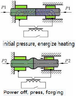
1, welding cycle
During resistance butt welding, the two workpieces are always pressed tightly. When the end face temperature rises to the welding temperature Tω, the distance between the end faces of the two workpieces is as small as a few
resistance butt welding-Schematic diagram
angstroms. The atoms between the end faces interact to produce common crystal grains on the joint. Form joints. There are two welding cycles in resistance butt welding: equal pressure and increased forging pressure. The former is simple and easy to implement. The latter is conducive to improving the quality of welding, and is mainly used for
resistance butt welding of alloy steel, non-ferrous metals and their alloys. In order to obtain sufficient plastic deformation and further improve the quality of the joint, a current upsetting procedure should be set.
2, process parameters
The main process parameters of resistance butt welding are: extension length, welding current (or welding current density), welding energization time, welding pressure and upsetting pressure.
(1) Overhang length l0 is the length of the workpiece over the end face of the clamp electrode. When selecting the extension length, two factors should be considered: the stability of the workpiece during upsetting and the heat dissipation to the clamp. If l0 is too long, the workpiece will lose stability during upsetting. If l0 is too short, due to the enhanced heat dissipation to the jaws, the workpiece will be cooled too strongly, which will increase the difficulty of plastic deformation. For the workpiece with diameter d, generally low carbon steel: l0=(0.5-1)d, aluminum and brass: l0=(1-2)d, copper: l0=(1.5-2.5)d.
(2) Welding current Iω and welding time tω In resistance butt welding, the welding current is often expressed by the current density jω. jω and tω are the two main parameters that determine the heating of the workpiece. The two can be adjusted accordingly within a certain range. High current density and short time (strong condition) can be used, or low current density and long time (weak condition) can be used. But when the condition is too strong, it is easy to produce incomplete penetration defects; when it is too soft, it will cause serious oxidation of the interface end surface, coarse grains in the joint area, and affect the strength of the joint.
(3) The welding pressure Fω and the upsetting pressure Fu, Fω have an effect on the heat generation and plastic deformation of the joint. Reducing Fω is good for heat generation, but not good for plastic deformation. Therefore, it is easy to use a smaller Fω for heating and a much larger Fu for upsetting. However, Fω should not be too low, otherwise it will cause splashing, increase end surface oxidation, and cause looseness near the interface.
3. Workpiece preparation
In resistance butt welding, the shape and size of the end faces of the two workpieces should be the same to ensure that the heating and plastic deformation of the workpieces are consistent. The end surface of the workpiece and the surface in contact with the clamp must be strictly cleaned. Oxide and dirt on the end face will directly affect the quality of the joint. The oxides and dirt on the surface of the workpiece in contact with the clamp will increase the resistance of the contact, which will cause the surface of the workpiece to burn, increase the wear of the jaws, and increase the power loss.
The workpiece can be cleaned by mechanical means such as grinding wheels, wire brushes, etc., or pickling.
Oxide inclusions easily occur in resistance welding joints. For rare metals, certain alloy steels and non-ferrous metals with high welding quality requirements, protective atmospheres such as argon and helium are often used to solve the problem.
Although resistance butt welding has the advantages of smooth joints, small burrs, and simple welding process, the mechanical properties of the joints are low, and the preparation of the end face of the workpiece is high, so it is only used for butt joints of small section (less than 250mm2) metal profiles.